
User Manual

Metallic Pipe
Earth
Ground
Grounding Clamp
Page 5
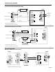
ELECTRICAL CONNECTIONS
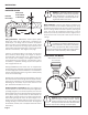
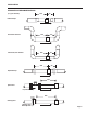
GROUNDING DIAGRAM
General Electrical Guidelines:
• Whenever possible avoid running control cables in
the same conduit with or bundled with AC power.
• Using shielded cable, be sure to connect shield to
ground at power supply end of the cable.
• Avoid routing ow sensor cables in close proximity to
a variable frequency drive.
• Recommended power and output wiring is shielded
twisted pair 18-22 AWG control cable.
• Recommended voltage is 12-24 Vdc. Note that
unregulated power supplies can vary from nameplate
voltage by a considerable amount, especially with AC
line voltage uctuation. Therefore 24V power supplies
must be regulated.
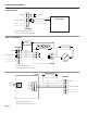
See the Connections diagrams on the following pages for the
appropriate terminals.
Power: A 12 - 24 Vdc power supply capable of at least 250
mA current output is needed.
Forward Flow Output: This open-collector isolated output
does not supply power. This pulse is generated in the forward
ow direction on the standard unit. (Reverse ow output is
available as an option).
Note: This output is limited to 6 mA at 30 Vdc maximum.
Reverse Flow Output: Reverse ow output is available as
an option. This open-collector isolated output does not supply
power. It functions like a polarity-sensitive switch closure.
Note: This output is limited to 6 mA at 30 Vdc maximum.
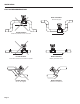
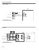
PLACE FERRITE BEAD HERE
Housing
Screw
Grounding Guidelines:
For best results, use a good quality earth ground, such as
metallic water piping or a driven ground, to ensure a good
connection to earth ground and good noise suppression.
If the ow sensor is installed in metallic piping, for optimum
connection clamp wire to the piping a short distance to one
side of the ow sensor using an electrical grounding clamp.
Connect the wire to the earth ground and to one of the housing
screws.
For Non-Metallic Pipe: Connect one to the housing screws
by wire to a good earth ground, such as metalic water piping
or a rod driven into the ground.
EX meters are usually unaffected by moderate levels of electri-
cal noise. In some applications performance may be improved
by taking the following steps:
• Use shielded twisted pair cable (Belden 8723 or
equivalent above ground or Alpha 35482 or
equivalent burial).
• Clamp a ferrite bead (Steward 28A2029-OAO or
equivalent) on meter signal/power wire within 3/4”
of the meter strain relief (tape or tie wrap in place
if necessary). See diagram below.
• IMPORTANT - Connect the cable shield ground
wire to ground, ONLY at power supply end of cable.
Caution: The EX800 has a strong start and
run current. When using solar panels and
VRSLA batteries as a power source, use
caution to insure the EX-series sensor has
the -50 Low-power Option and that all Seametrics
products on the power circuit receive sufcient volt-
age and current under all conditions. Failure to do so
will lead to unreliable operation and possible damage
to the unit/s. Please reference the technical bulletin,
‘Solar and Battery-Power Guildlines’ available on our
website: www.seametrics.com