FT400-Series • FT415 • FT420 ISO 9 0 0 1 : 2 0 0 8 CERTIFIED COMPANY F T 4 0 0 - S E R I E S R AT E T O TA L / I N D I CAT O R I N S T R U C T I O N S RATE/TOTAL INDICATOR INSTRUCTIONS
TABLE OF CONTENTS General Information General Information, Features, Specifications................................................................................................... Page 1 Installation Wall Mount, Meter Mount, Panel Mount............................................................................................................ Page 2 Connections, FT420 Option 98, -98 Relay Board Specifications......................................................................
GENERAL INFORMATION The FT400-Series flow computers are microcontroller-based indicator/transmitters that display flow rate and total and provide output signals. The FT415 is battery-powered and provides a scalable pulse output. The FT420 is powered by external DC voltage and has both pulse and 4-20 mA analog outputs. When the FT420 is being used in the 4-20 mA mode, it is a “two-wire” or “loop-powered” device, meaning that the 4-20 mA output signal doubles as its power supply.
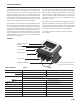
INSTALLATION Wall Mount. To mount an FT400-Series indicator to the wall, hold the unit in the desired position, mark the holes in the mounting feet, drill and mount with screws. With the FT420W-65 option, first remove the front cover to gain access to the mounting screw holes. Meter Mount Sensor Wires Sensor Wires A meter-mounted FT400-Series can be converted to a wall mount using an MK20 mounting kit. Meter Mount.
INSTALLATION Connections. To connect the FT400-Series flow computer to a flow sensor or an external device such as a chemical metering pump, follow the Standard Connections diagrams on pages 4-6. If the FT420's 4-20 mA current signal is not required, connect the power terminals to any 12-30 Vdc voltage source. Dual Relay Output (Option -98). If you purchase the FT420 with option 98, the required component will come preinstalled, and no extra procedures are required.
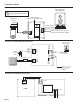
CONNECTION DIAGRAMS FT415 Standard Connections Pulse Responsive Metering Pump Caution: Do not apply external power to the FT415.
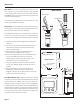
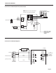
CONNECTION DIAGRAMS Connections for FT420-98 (Dual Relay Output Option) Electronic Metering Pumps NOTE: Outputs may be paralleled to switch up to 200 mA AC/DC - + - PULSE PASSTHRU - - 12-32 Vdc Loop Power Supply POWER 4-20 mA + + Relay Board white wire + Isolated Contact PULSE SCALED - 30221 S Flow Sensor + SENSOR INPUT Red White Black red wire (Passes flow sensor pulse on to another control without scaling) Connections for FT420/EX Magmeter 24 Vdc Power + FT420 Red _ Power +
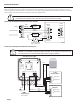
CONNECTION DIAGRAMS FT420 Display with 4-20 mA Output When running the FT420 with a magmeter (which requires power), the FT420 must be connected to two power supplies, one for the magmeter and one for the 4-20 mA loop. You may either use a dual power supply (available from Seametrics as the PC42), or two single power supplies (one of which may be the 4-20 mA loop itself). See diagrams below.
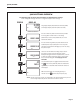
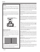
(QUICK) SETTINGS QUICK SETTINGS OVERVIEW See following page for step-by-step instructions on changing these settings Pass through all settings and return to original display to save settings. PRESS DISPLAY 0.00 209.8 MIN Large digits display instantaneous flow rate (GPM). Small digits display total flow (since last reset). RESET START UP DISPLAY SET SET K SET 00001.000 0000010.0 SET P SET 0001000.0 SET 20 d SET SET 209.
SETTINGS K-FACTOR At a minimum, every FT400-Series flow computer must be programmed with the “K-factor”. (This is the number of pulses that the meter produces per gallon of flow.) If you wish the FT400 to read in units other than gallons, see below. The K-factor on any Seametrics flow sensor fitting or in-line meter can be found on the model-serial label. The line reading K = xxxx gives the desired number. For depth-adjustable sensors (110, 210, 150, 250 models), use the calculator on our website.
OPERATION Resettable/Non-Resettable Totalizer. Unless the unit has been ordered with the non-reset option, a RESET prompt is visible in the lower right corner above the up arrow key, when the display is in use. Press the up arrow key at any time to reset the totalizer to zero. (Note: If you need to reset a unit that has been ordered with a non-resettable totalizer, contact your distributor.) (either standard electronic or relay-type), it should pulse for 0.
TROUBLESHOOTING Probable Cause Problem Try...