Save This Manual For Future Reference BELT AND DiSC SANDER I Serial Number J _ RS/CRRFTSMRN Model and serial number may be found on the back side of the base BELT AND DiSC SANDER You should record both model and serial number in a safe place for future use. FOR YOUR SAFETY: • assernbly ° operating o repair parts READ ALL INSTRUCTIONS CAREFULLY _,, J _, Sold by SEARS, ROEBUCK Part No. SP5406 ,,_ AND CO., Chicago, IL. 60684 U.S.A.
FULLONE YEAR WARRANTY ON CRAFTSMAN BELT AND DISC SANDER If with In one year from the data of purchase, th Is Craftsman BeIt and Disc Sander fails due to a defect in mater lal or workmanship, Sears will repair it, free of charge. WARRANTY SERVICE IS AVAILABLE BY SIMPLY CONTACTING DEPARTMENT THROUGHOUT THE UNITED STATES. THIS WARRANTY THE NEAREST SEARS SERVICE CENTER/ APPLIES ONLY WHILE THIS PRODUCT IS USED iN THE UNITED STATES.
BEFORE EACH USE: Inspect your sander. PLAN DISCONNECT THE SANDER. To avoid injury from accidental starting, unplug the sander, turn the switch off and remove the switch key before changing the setup, sanding disc or belt or adjusting anything. KNOW YOUR SANDER. Read and understand the owner's manual and labels affixed 1o the tool. Learn its application and limitations as well as the specific potential hazards peculiar to this tool. AHEAD HANDS, CHECK DAMAGED PARTS.
safety instructions for belt and disc sander • Wear nonslip footwear. • Noise levels vary widely. To avoid possible headng damage, wear ear plugs or muffs when using sander for hours at a time. - Sanding operations are usually dusty. Wear a dust mask along with the safety goggles. Inspect your workplece Make sure there are no nails or foreign objects in the part of the workpiece to be sanded.
motor specifications and electrical requirements This machine is designed to use, and is equipped with, a3450 RPM motor. It is wired foroperation on 120 volts, 60 Hz., alternating current. WARNING: To avoid electrocution or fire, tool must not be converted to operate on 240 volts. For replacement motor, refer to parts list in this manual. CONNECTING OUTLET TO POWER SUPPLY This machine must be grounded while in use to protect the operator from electric shock. grounded in accordance nanaces.
contents POWER TOOL WARRANTY ......................... SAFETY INSTRUCTIONS FOR BELT D)SC SANDEF ............................................. MOTOR SPECIFICATIONS AND ELECTRICAL REQUIREMENTS ........................... UNPACKING AND CHECKING CONTENTS ............ ASSEMBLY ................................................................ Mounting Belt and Disc Sander to Workbench .................................................... Clamping Belt and Disc Sander to Workbench ...................................
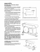
assembJy MOUNTING BELT AND DISC SANDER TO WORKBENCH If belt and disc sander is to be used in a permanent location, itshould be fastened securely to a firm supporting surface such as a workbench, 24 MIN. OUTLINE If mounting to a workbench, holes should be drilled through supporting surface of the workbench using dimensions illustrated. OF SANDER 3/8 2 DIAMETER HOLES _____ r ............. h 1. The u nit should be bolted securely using 5/16" screws and hex nuts (not included).
assembly INSTALLING SANDING DiSC AND GUARD SANDING PLATE 1. Locate sanding disc and pee backing from disc. Align perimeter of disc with I_late and press disc firmly into position all the way around. 2. Locate disc guard and two pan head screws, M4,2 x 1.4-12 from loose Darts bag. 3. Position disc guard against lower 1/3 of disc aligning holes as shown. 4. Using phillips type screwdriver, fasten the pan head screws securely applying slight pressure to thread the holes.
/// 4. Locatewasher pads, 6.5 x 17.8 x 1.6 and knob among loose 5. Position table support in corresponding holes on side of base as shown. Make sure the 9.5ram diameter index pin aligns with upper hole, 6, Place washer on threaded shaft of knob and insert through slot into threaded holes of base SUPPORT WARNING: To avoid trapping the work or fingers between the table and sanding surface, the table edge should be a maximum of 1/16 inch from sanding surface.
assembly AUXILIARY SANDING MOUNTING FOR VERTICAL f J 1. Remove backstoplock bolt and removework support. 2. Removetable assembly by removingtable lock knob and washer. AUXILIARY < MOUNTING HOLES NOTE: Beitbed may be raised to vertical position by loosening he× socket screw and raising bed. See "PositioningBelt Bed" on page 16. 3. Attach table assembly to auxiliary holes in belt bed. Make sure index pin is in the upper hole when sanding table is in the vertical position.
TENSION LEVER 3. Slide tension lever to the left to apply belt tension. 4. Tighten hex socket screw when bed is in desired position. 5. Plug in the power cord. Turn switch "ON" and immediately "OFF," noting if the belt tends to slide off the idler pulley or drive pulley. If it did not tend tOslide off, it is TRACKING properly. TRACKING KNO_ 6. If the sanding belt moves toward the disc, turn the tracking knob clockwise 1/4 turn. 7.
4 TENSION LEVER 6 AUXILIARY MOUNTING HOLE / WORK SUPPORT HEX SCREW BED 2 BED LOCKING HEX SOCKET HEAD SCREW 3 TRACKING KNOB 5 TABLE LOCK KNOB HOLE 1 WORK SUPPORT SANDING BELT SANDING PLATE SANDING DISC / WORKTABLE ASSEMBLY DISC GUARD 7 ON-OFF SWITCH MOUNTING HOLE WARNING: To avold injury from accidental start, turn switch "OFF" and remove plug from power source outlet before making any adjustments. 4. Tension Lever.
ON-OFF SWITCH The On-Off switch has a locking feature. THIS FEATURE IS INTENDED TO HELP PREVENT UNAUTHORIZED AND POSSIBLY HAZARDOUS USE BY CHILDREN AND OTHERS. 1. To turn machine "ON" insert key into switch. NOTE: Key is made of yellow plastic, located in loose parts bag, 2. Insert finger under switch lever and PULL end of switch out. 3. To turn machine "OFF".. PUSH lever in. NEVER LEAVE THE MACHINE U NATrENDED IT HAS COME TO A COMPLETE STOP. UNTIL 4.To lock switch in OFF position..
BEFORE USING THE SANDER To avoid Injury from jams, slips or thrown pieces. USEONLY RECOMMENDEDACCESSORIES. WARNING: To avoid mistakes that could cause serious, permanent injury, do not plug the sander in untU the following steps are comp|eted. - Assembly and alignment. (See pages 7 - 11 } = Learn the use and function of the ON-OFF switch. backstop, belt tracking knob, belt tension lever, work table and work table tilt lock knob.
Dressfor safety, Sand only one workpiece at a time. Any power sander can throw foreign objects into the eyes. This can cause permanent eye damage. Wear safety goggles (not glasses) that comply with ANSI Z87.1 (shown on package). Everyday eyeglasses have only impact resistant lenses. They are not safety glasses. Safety goggles are available at Sears retail catalog stores. Glasses or goggles not in compliance with ANSI Z87.1 could seriously hurt you when they break.
bas ic operation BEVEL SANDING The worktable can be tilted from 0oto 45 ° for bevel sanding. Loosen the table lock knob and tilt the worktable to desired angle as shown. Retighten table lock Knob. TABLE WARNING: TO avoid trapping the work or fingers between the table and sanding surface, the table should be reposltioned on the table support to retain a maximum of 1/16 Inch distance between sanding surface and table.
SURFACE BELT SANDING ON THE SANDING WARNING: To avoid injury from sflps, jams or thrown pieces, adjust the backstop to clear the sanding surface by no more than 1/16 of an inch. When checking clearance between the belt and work support, press the belt flat against the metal beneath it. WORK SUPPORT WORKPIECE SANDING BELT Hold the workpiece firmly with both hands, keeping fingers away from the sanding belt. Keep the end butted against the backstop and move the work evenly across the sanding belt.
basic operation Always sand outside curves on the left side ofcenter on the sanding disc as shown. WARNING: Applying the workplece to the right side of the disc could cause workplece to fly up (kickback) and result In an Injury. WORKPIECE SANDING DISC SANDING SMALL END SURFACES THE SANDING DISC MITER GAUGE ACCESSORYI ON \ \ NOTE: Use of a Miter Gauge (optional accessory) is recommended for this operation.
maintenance WARNING: For your own safety, turn switch "OFF" and remove plug from power source outlet before adjuSting, maintaining, or lubrlcsting your belt and disc sander. WARNING: TO avoid electrocution or fire, any repairs to electrical systems should be done only by qualified service technicians. Unit must be reassembled exactly to factory specifications. BLACK BLACK JUMPER POWER If powercord is worn orcut, ordamaged in anyway, have it replaced immediately.
maintenance 4. Slightly tighten (3) screws. Adjust tension of belt by putting blade screwdriver in adjusting hole. Push up on screwdriver to tighten tension between pulleys. 5 Tighten screws being careful not to disturb belt. STANDARD SCREWDRIVER \ ADJUSTING HOLE 6. Test belt tension by placing fingers on either side of belt and squeeze. There should be about a 1/4" give to the belt. NOTE: Excessive tightness on pulley belt may cause increased noise and over load motor.
troubleshooting WARNING: For your own safety, turn switch "OFF" and remove plug from power source outlet before troubleshooting your sander. TROUBLE Motor will not run. Machine slows down when sanding, PROBABLE CAUSE REMEDY 1. Defective On-Off switch Defective switch cord. Defective switch box. 2. Burned out motor. 1. Replace defective parts before using belt disc sander again. 1. Timing belt too tight. 1.
repair parts o \ ! / 22
repair parts PARTS LiST FOR CRAFTSMAN BELT AND DiSC SANDER MODEL 113.226430 Key No. Part No.
BELTAND DISC SANDER SERVICE MODEL NO. 113.226430 HOW TO ORDER REPAIR PARTS Now that you have purchased your Belt and Disc Sander, should a need ever exist for repair parts or service, simply contact any Sears Service Center and most Sears, Roebuck and Co. stores. Be sure to provide all pertinent facts when you call or visit. The model number of your Belt and Disc Sander will be found on a plate attached to your sander on the back side of the base.