Save This Manuat For Future Reference MODEL NO. / e / 113.243300 SAW ONLY / / / '/ / MODEL NO. / / / \ 113.243311 .\ SAW WITH LEGS AND MOTOR Serial Number Model and serial number may be found at the right-hand of the frame, side You should record both model and serial number I in a safe place for future use. 12-iNCH SANDER CAUTION: Read GENERAL ADDITIONAL = assembly and SAFETY • operating INSTRUCTIONS carefu|ly Sold by Part No.
FULL ONE YEAR WARRANTY If within one year from the date of purchase, or workmanship. Sears will repair it, free WARRANTYSERVICE IS AVAILABLE CENTER/DEPARTMENTTHROUGHOUT THiS WARRANTY This warranty to state. APPLIES gives SEARS. general ONLY ON CRAFTSMAN this Craftsman Band Saw fails due to a defect THiS PRODUCT THE IS IN legal rights, and you may also have other ROEBUCK AND safety in materia! 698/731A, instructions Sears Tower, for NEARESTSEARS USE you specific CO..
Safety is a combination of alertness at all times when h. When cutting a large piece is supported at table height. operator common sense and the band saw is being used. i. Hold the work FREEHAND WARNING: FOR YOUR OWN SAFETY, DO NOT ATTEMPT TO OPERATE YOUR BAND SAW UNTIL mT tS COMPLETELY ASSEMBLED AND INSTALLED ACCORDBNG TO THE INSTRUCTIONS , .. AND UNTSL YOU HAVE READ AND UNDERSTOOD THE FOLLOWING: 2. Getting Safety Instructions To Know Your Band Saw/Sander 3. Basic Band Saw Operation 4.
additional safety instructions for band saw/sander WARNING: DO NOT ALLOW FAMiLIARiTY (GAINED FROM FREQUENT USE OF YOUR BAND SAW) TO BECOME COMMONPLACE. ALWAYS REMEMBER THAT A CARELESS FRACTION OF A SECOND iS SUFFICIENT TO iNFLICT SEVERE iNJURY. WARNING: THE 5" BAND SAW PULLEY AND THE 2-I/2" MOTOR PULLEY FURNISHED, WILL RUN THE BLADE AT APPROXIMATELY 900 RPM (OR 2700 FEET PER MINUTE) WHEN USED WiTH A 1725 RP_ MOTOR. NEVER SUBSTITUTE THESE PULLEYS TO iNCREASE THIS SPEED BECAUSE IT COULD BE DANGEROUS.
motor specifications Qnd eledrkai This machine is designed to use a 1725 RPM motor only. Do not use any motor that runs faster than 1725 RPM. It is wired for operation on 110-120 volts, 60 Hz., alternating current. (TOOL MUST NOT BE CONVERTED TO OPERATE ON 230 VOLT EVEN THOUGH SOME OF THE RECOMMENDED MOTORS ARE DUAL VOLTAGE, CHANGING TO 230 VOLT WILL NOT CONSERVE ENERGY AND REQUIRES CHANGING THE POWER CORD PLUG AND MOTOR RECEPTACLE. THESE CRAFTSMAN MOTORS FOUND TO BE ACCEP1ABLE THIS TOOL.
unpackm°n g and checking contents CONTENTS UNPACKING ASSEMBLY AND CHECKING CONTENTS ....... Blade Guide 6 Lateral Assembling Steel Legs ........................ Saw/Sander 7 Mounting Band on Leg Set ........ 8 Installing Installing Motor. Pulley. V-Belt. and Belt Guards 8 Sawdust Elbow ................... 11 Installing Table ............................. 12 Installing Blade ............................. 1 2 Adjusting the Table ......................... On-OH Switch ...........
THE FOLLOWBNG MODEL I 13,24331 PARTS' 1 ONLY. ARE iNCLUDED WiTH Description totem Qty. 1 I Nut, He× Head 1/2-13 A A *NutHex B "Screw C 1/4-20 .............. Truss Hd. Lockwasher, D E F " Foot, Motor 1/4-20 x 5/8 1/4 External ..... 8 I 32 1 32 ....... 32 Leveling ............... ..................... Leg ....................... Channel, Support G H .......... .............. J Stiffener, Stiffener, Side ................ End ...................
assembly MOUNTING BAND SAW/SANDER ON LEG SET LE FT FOOT \ NOTE: For illustrative purposes, the Band Saw is shown mounted on the Craftsman Catalog No. 9-22236 Steel *Leg Set. This Leg Set is included with Model No. 113.243311. RIGHT FOOT CHECK 1. Remove the Band Saw cover by applying gentle pressure on the spring tabs and release the top of the cover by pulling it away from the frame. procedure for bottom portion of cover NOTE: Check Saw as shown.
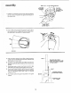
HUB SET SCREW _" 4. Place the large pulley onto the drive wheel shaft and insert the key into the keyway of the shaft and pulley. Position pulley hub flush with end of shaft and tighten set screw securely against key. FLUSH HER£ ! 3/16" KEY Ilili KEYWAY iN SHAFT AND PULLEY / LOCKWASHER FLAT WASHER -NUT CARRIAGE BOLT 5/16-18 x 3/4 5. Place motor against the motor mounting bracket and insert bolts through holes in motor base and then through holes marked "'X" in motor mounting bracket.
assem61y SMALL [2-9/2" DIA,) MOTOR 5/32 INCH SETSCREW WRENCH \ PULLEY TIGHTEN SET SCREW AGAINST FLAT ON SHAFT \ \ 7. Install the small pulley ontothe motor shaft and tighten the se_ screw _n the pulley hub against the flat part of the motor shaft, / PULLEY FLUSH HERE WITH MOTOR SHAFT 8. Push V-Belt partly through belt guard enough to allow belt to loop around the large pulley and push guard ove r belt and pulley into position on guard support -1 / / ,/ I \ OPEN END 9.
14. Route motor cord up and around backside of saw frame. Plug motor saw frame screw. INSTALLING 1. Remove front cord into outlet on upper and secure cord with the SAWDUST the Band leg and along section of band cord clamp and ELBOW Saw cover by applying gentle side SELF-THR EADING SCREW pressure on the spring tabs and release the top portion of the cover by pulling it away from the frame. Repeat procedure for bottom portion of cover. 2.
assembly INSTALLING Apply TABLE TRUNNION TABLE a coat of automobile wax to the table. 1. Place the table on the band saw so that the two trunnion pins and the trunnion. table lock bolt go through the slot 2. Find the 1-1/8" din. flat washer, a sleeve 11/16" the trunnion lock nut and the table lock handle among 3. Hold tn the long, from the loose parts. the head of the table lock bolt inside the band saw with your left hand and oul the 1-1/8" the sleeve, and the handle on the bolt. din.
UPPER THRUST BEARING 1/8" SETSCREW WRENCH 4. Loosen the two setscrews which lock guides and separate them about 1/8". Do that table. same thing to the See Step 6 for location lower the guides upper beneath blade the of setscrew. _ THRUSTBEARIN! ADJ. 5. SETSCREWS i tl / UPPER J t :_ /1[8" THRUST BEARING KNOB SETSCREW WRENCH Loosen the setscrew which locks the upper thrust bearing and turn the knob until the thrust bearing is all the way back as shown.
assembly TO AVOID BEING SCRAPED SHOULD BLADE SUDDENLY UNCOIL WEAR SAFETY GOGGLES AND CAREFULLY UNCOIL THE BLADE HOLDING iT AT ARMS LENGTH. POINTER _--TENSION 7. Carefully uncoil the blade, holding it at arms length. ADJ. KNOB 8. Place the blade over the wheels with the teeth pointing downwards toward the table as shown. Make sure the blade is between the rubber tl res.
NOTE: The upper and lower blade guides support the blade and keep it from twisting during operation. An adjustment is necessary when blades are changed or replaced. 14. To adjust the upper blade guides loosen the setscrew which locks the blade guide holder (see illustration). APPROX. 1/32"' BLADE GUIDE !5. Turn the blade guide adjustment knob, so that the guides move toward the blade, Move them until the "ledge" is about 1/32" from the deepest part of the blade teeth. This deep part is called a "gullet".
assembJy ON-OFF SWITCH WARNING: DON'T CONNECT POWER COR D TO ELECTRICAL OUTLET IN YOUR SHOP UNTIL YOU ARE SURE THAT MOTOR ROTATION IS CORRECT. (SEE PAGE 5). The On-Off Switch has a locking feature, THIS FEATURE IS INTENDED TO PREVENT UNAUTHORIZED AND POSSIBLY HAZARDOUS USE BY CHILDREN AND OTH E RS. 1. Insert key into switch. NOTE: Rk_k Key is made of yellow 2. To turn machine on. insert pull end of switch out. 3. To turn Never machine leave to a complete band saw. 4. the OFF.
geffing to know your band saw/sander 2 /--TENS,ON A UST, NG K.OB-COVER.ETAINING CL,P"\ 8 GUIDE BAR LOCK SCREW 3 TENSION (Inside) SCALE CORD OUTLET "7 THRUST BEARING ADJ. KNOB (Lower Knob Not Shown) TI LT LOCK HANDLE \ SAW PULLEY BLADEGUIDE ADJ. KNOB (Lower Knob Not Shown) BA CK FRONT 1. ADJUSTMENT DIAGRAMS . . . Help you to become familiar with the adjustments, 5. 2. TENSION ADJUSTMENT KNOB . . . Tightening the knob will increase the tension on the blade.
getting to know your band saw/sander 9. GUIDE BAR When the upper guides are raised or lowered, they must not deflect the blade sideways. This means th at the guide bar must be parallel to the blade, or square with the table. SCREW 1. Remove the blade guard, cover, blade, and the upper guide assembly. 2. Lower 1-3/4" the guide bar until from the table. 3. Hold 4.
6, Attach the sanding platen to the guide bar with the same screw that held the upper blade guide assembly. Do not tighten the screw at this time. On the smooth side of the sanding belt, you will find a "directional arrow". The belt must run in the direction of this arrow so that the splice does not 7. Place the belt on the wheels and knob until the pointer points to upper wheel by hand a few times to belt is tracking properly and is not come apart, 3 tighten the tension SAND.
basic band saw/sander BASIC BAND SAW/SANDER operation OPERATION A band saw is basically a "curve capable of doing inside cutting. cutting" machine. It is no_ Your Craftsman Band Saw/Sander is no_ only capable of the usual band saw operations, out it can he converted into a sander as well. You can finish wood, certain compositions and plastics and non-ferrous metals. It is also used for stra ght-line crosscutting, ripping, mitering, and resawing.
maimtenamce WARNING: FOR YOUR OWN SAFETY, TURN SWITCH "OFF" AND REMOVE PLUG FROM POWER SOURCE OUTLET BEFORE MAINTAINING OR LUBRICATING YOUR BAND SAW, GENERAL ON-OFF SWITCH t__o o_3. MAINTENANCE Pitch and sawdust that accumulate on the tires should be removed with a stiff brush or scraped off with a piece of wood. Do not use a sharp knife or any kind of solvent. POWER CORD A E GREE Do not allow pitch to accumulate on the table, the insert, the guides or the thrust bearings.
trouble shooting WARNING: FOR YOUR OWN SAFETY, TURN SWITCH "OFF" AND REMOVE SOURCE OUTLET BEFORE TROUBLE SHOOTING YOUR BAhiD SAW/SANDER. TROUBLE PROBABLE Blade does not run in the approximate center of the Blade does not run in the approximate center of the lower wheel, Band Saw slows down when cutting. 1. Not tracking 1. Lower CAUSE properly. wheel not correctly on pivots 3, Cutting too 4. Dull REMEDY 1. Adjust tracking, see Assembly "Installing the Blade." positioned 1.
TROUBLE TROUBLE Motor starts siow{y or faiJs to come up to full speed. SHOOT_NG PROBABLE t. Low voltage trip relay. 2. Windings or open. 1. Motor will REMEDY not burned 1. Request out not cooling. {Air restricted 1. Burned switch contacts 1, Starting switch operating. repaired 3. Have relay replaced. 1. Feed slower work from the power company. or replaced. into blade. to provide normal air motor, and Lubrication" section 1.
CRAFTSMAN 12-INCH BAND SAW/SANDER, MODEL 113.243300 & 113.243311 "tO Q _o ,/ / SEE FIGURE FOR EXPLODED VIEW 32 14 f \ / 46 m 45 _.I.
CRAFTSMAN 12-iNCH BAND SAW/SANDER, Always order by Part Number FIGURE PART NO. IKEY NO. 69069 41815 38524 37158 41711 STD315228 69028 41812 10 11 12 13 14 15 16 17 18 19 20 21 22 23 Frame with Trim Screw, Self-Locking Ring, Retaining 5/8 Washer, Spring Bearing, Ball Wheel, Upper Drive Ring, Internal Retaining 1-3/8 Key, Switch Clip *Bearing, Ball Ring, Interna! Retaining 1-11/16 *Screw, Type "'T" 10-32 x 1/2 *Key, Square 3/16 x 1-1/4 *Screw, Set, 5/16-18 x 1/2, Soc. Hd., Cup Pt.
CRAFTSMAN 12-INCH BAND SAW/SANDER, MODEL 113.243300 & 113.243311 Q FOR WIRING DIAGRAM SEE PAGE 26 67 me =0 Q 68 \ I I [ 9 10 2o 44\ O' I 12 13 14 I 18 7i \ 16 12 17 FIGURE 2 "_"'"_ 2o 6
CRAFTSMAN 12-INCH BAND SAW/SANDER, FIGURE PART NO.
CRAFTSMAN 12-tNCH BAND SAW/SANDER, 3 ---'--e MODEL el'_'--" 113.243300 /,-'7 4 /'/7 SUPPUED Key , No, 1 2 3 4 5 6 7 8 9 10 FIGURE MODEL WiTH Part 3 113.
CRAFTSMAN 12-iNCH BAND SAW/SANDER, MODEL 113.243300 & 113.243311 NOTE: ANY ATTEMPT TO REPAIR THIS MOTOR MAY CREATE A HAZARD UNLESS REPAIR IS DONE BY QUALIFIED SERVICE TECHNICIAN. 3 REPAIR SERVICE IS AVAILABLE AT YOUR NEAREST SEARS STORE. \ \ \ @- FIGURE SUPPLIED Key No. 4-MOTOR PART NO. 69183 WiTH MODEL 113.243311 ONLY Part No. 60306 Description Screw, 8-32 x 3/8, Cutting, Slotted, Hd.
NOTE5 30
NOTES 31
SERVICE Now that you Saw!Sander parts should or service, Center MODEL NO. 113.24330(} have purchased and a need simply most your ever contact Sears, 12-Inch exist Band for repair any Sears Service Roebuck Be sure to call or visit. provide all pertinent The number of your and Co. stores. facts when you SAW ONLY MODEL NO. 113.243311 model Sander will be found hand side of the saw.