® OWNER’S MANUAL MD Model No. 139.18847 139.18857 ® GARAGE DOOR OPENER 1/2 HP The Chamberlain Group, Inc. Cover - SEARS 4/16/92 For Residential Use Only ■ Caution: Read and follow all safety rules and operating instructions before first use of this product. ■ ■ ■ ■ ■ ■ Fasten the manual near the garage door after installation. ■ Safety Precautions Assembly Installation Adjustment Care and Maintenance Operation Troubleshooting Parts List ® Sears Canada, Inc.
Contents Page A review of safety alert symbols.................................2 You'll need tools..........................................................3 Safety information regarding garage door locks and ropes.........................................................3 Testing your garage door for sticking, binding and balance..................................................3 Illustration of sectional door installation .....................4 Illustration of one-piece door installation ..................
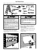
You'll Need Tools During assembly, installation and adjustment of the opener, instructions will call for hand tools shown below. Pencil Carpenter's Level Hack Saw 2 1 Tape Measure Wire Cutters WARNING Claw Hammer Drill 3/16", 5/16", and 5/32" Drill Bits Stepladder Pliers Adjustable End Wrench Screwdriver 1/2" and 7/16" Sockets and Wrench WARNING CAUTION WARNING To avoid damage to the garage door and opener, disable locks before installing and operating the opener.
FIN Su fa SECTIONAL Door Installation vertical reinforcement Before you begin, survey your garage area to see whether anyHorizontal of the and conditions below apply to your installation. is needed for lightweight garage doors (fiberglass, steel, aluminum, door with glass panels, etc.). See page 24 for details. Horizontal and vertical reinforcement is needed for lightweight garage doors (fiberglass, steel, aluminum, door with glass panels, etc.). See page 24 for details.
One-Piece Door without Track ONE-PIECE Door Installation Before you begin, survey your garage area to see whether any of the conditions below apply to your installation. FINISHED CEILING Support bracket & fastening hardware may be required. See page 17. Slack in Chain Tension is Normal When Garage Door is Closed Header Wall Closed Position Cable Pulley Bracket Access Door Trolley Cable Header Bracket T-rail The Chamberlain Group, Inc.
Opener Carton Inventory Your garage door opener is packaged in two cartons which contain all parts illustrated below. If anything is missing, carefully check the packing material. Parts may be "stuck" in the foam. Hardware for assembly and installation is shown on page 7.
Group all hardware found in all packages contained in the rail and opener cartons into the three kits illustrated below. Assembly Hardware Kit 41A3534 Hex Screw 5/16"-18x7/8" (3) Washered Screw 5/16"-18x1/2" (2) (mounted in opener) Nut 5/16"-18 (5) Carriage Bolts 1/4"-20x1/2" (4) Master Link (2) Lock Nut 1/4"-20x7/16" (4) Lock Washer 5/16" (4) Trolley Threaded Shaft (1) Installation Hardware Kit 41A3475-4 ASE GRE RAIL .
Assemble Tee Rail & attach Cable Pulley Bracket Assembly Section: Pages 8 – 11 SEARS '92 (525) Assemble Tee Rail Pulley Bracket To avoid installation difficulties, do not run the garage door opener until instructed to do so.
The Chamberlain Group, Inc. Step 2 Install Trolley & Attach Chain Retainer Bracket The Sears Chamberlain Group, Inc. Hardware Shown ChassisStep Assembly 2 Actual Size Step4/12/92 2 Install Trolley & Attach Chain Retainer Bracket Install the Trolley on the T-rail Sears Chassis 4/12/92 • Attach the threaded shaft to the trolley with the lock washer and nuts as shown.
s ng Assembly The ChamberlainStep Group,4Inc. WARNING Install the Chain/Cable & - Sears Chassis Step 4 Install Chain & Cable Group, Inc. Serious injury can result if fingers become AttachThe theChamberlain Sprocket Cover Opener 4/10/92 Sprocket entangled in moving opener sprocket. Attach Step 4 Install Chain & Cable - Sears Chassis sprocket cover securely. Never operate opener Opener 4/10/92 Dispensing Carton while your hand is near the opener sprocket. The Chamberlain Group, Inc.
Assembly Step 5 Patin du rail Tighten the Chain & Cable • Spin the inner nut and lock washer down the threaded shaft, away from the trolley. • To tighten the chain, turn outer nut in the direction shown. As you turn the nut, keep the chain from twisting. • When the chain is approximately 1/2" above the base of the T-rail at its midpoint, re-tighten the inner nut to secure the adjustment. Sprocket noise can result if chain is either too loose or too tight.
Installation Section: Pages 12 – 27 TheGroup, Chamberlain Group, Inc. The Chamberlain Inc. Position SECTIONAL PositionGroup, Header Bracket SECTIONAL DOOR AND DOOR AN Installation Step 1 Header Bracket The Chamberlain Inc.
One Piece Door Without Track 1/30/92 - 4/7/92 Header Wall Header Wall Unfinished Unfinished Ceiling Ceiling Vertical Vertical Centerline Centerline ONE-PIECE Door Without 2x4 2x4 Track Structural Structural supports supports Read the Safety instructions on page 12. They also apply to doors without tracks. Unfinished Ceiling Header Wall • Close the door and mark the inside vertical centerline of your garage door. Extend the line onto the header wall above door.
You can attach the header bracket either to the wall above the garage door, or to the ceiling. Follow the instructions which will work best for your particular requirements.
Attach Tee Rail to Header Bracket 2/4/92 - 4/9/92 Installation Step 3 Attach the T-rail to the Header Bracket • Position the opener on the garage floor below the header bracket. Use packing material as a protective base. If the door spring is in the way you'll need help. Have someone hold the opener securely on a temporary support to allow the T-rail to clear the spring. • Position the cable pulley bracket against the header bracket. • Align the bracket holes and join with a clevis pin as shown.
Porte Installation Step 4 CAUTION Disconnect and Lockout PositionManual the Opener Searsapply -92 to your door Follow instructions which type as illustrated. 9/7/90, 3/2/92 Escabeau To prevent damage to steel, aluminum, fiberglass or glass panel doors, do not rest the opener on the door without using a 2x4.
Solives Installation Step 5 WARNING Hang the Opener The opener could fall and injure someone if it is not properly secured. Fasten the opener securely to structural supports of the garage. Tire-fond de 5/16 de po-18 x 1-7/8 de po Solives Mesurer la distance Tire-fond de Two representative installations are shown. 5/16 de po-18 x 1-7/8 de po Yours may be different. Hanging brackets should Mesurer la distanceFigure 1, to provide rigid support.
CAUTION Installation Step 6 WARNING Install the Door Control Do not connect to live electrical wiring. Connect only to 24 Volt low voltage wires. Connection to live wires or higher voltage may cause serious injury from shock, burn or electrocution. Children operating or playing with a garage door opener can injure themselves or others. The garage door could close and cause serious injury or death.
6. Attach the User Safety Instruction label to the wall near the door control, and the Maintenance Instruction label in a prominent location on the inside of the garage door. Do NOT connect the power and operate the opener at this time. The trolley will travel to the full open position but will not return to the close position until the sensor beam is connected and properly aligned. See Safety Reversing Sensor instructions beginning on page 21. Page 32 explains how to use the door control.
Installation Step 9 Electrical Requirements To prevent electrocution or fire , installation and wiring must be in compliance with local electrical and building codes. Do NOT use an extension cord, 2-wire adapter, or change the plug in any way to make it fit your outlet. To reduce the risk of electric shock, your garage door opener has a grounding type plug with a third grounding pin. This plug will only fit into a grounding type outlet.
The Safety Reversing System Information you'll need before you begin the installation of the safety reversing sensor. The safety reversing sensor must be connected and aligned correctly before the garage door opener will move in the down direction. This is a required safety device and cannot be disabled. WARNING Without a properly working safety reversing sensor, persons (particularly children) could be injured or killed by a closing garage door. Read and follow all instructions.
Installation Step 10 Install the Safety Reversing Sensor Figure 2 Figures 2 and 3 show assembly of brackets and "C" wrap based on the recommended installation of the sensors as shown on page 21. However, Figures 4 and 5 are variations which may fit your installation requirements better. Make sure the wraps and brackets are aligned so the sensors will face each other across the garage door. • Fasten the "C" wraps to the mounting brackets having square holes, using the hardware shown in Figure 2.
• Center each sensor unit in a "C" wrap with lenses pointing toward each other across the door (see Figure 6). • Secure sensors with the hardware shown. Finger tighten the wing nut on the receiving eye to allow for final adjustment. Securely tighten the sending eye wing nut. • Run the wires from both sensors to the opener. Use insulated staples to secure wire to wall and ceiling. • Strip 1/4" of insulation from each set of wires.
Door Bracket-Sectional Installation Step 6/96Fasten Door Bracket 11 CAUTION To prevent damage to steel, aluminum, fiberglass or glass panel doors, always reinforce the inside of the door both vertically and horizontally with an angle iron. Follow instructions which apply to your door type as illustrated below or on page 25. A horizontal brace should be long enough to be secured to 2 vertical supports. A vertical brace should cover the height of the top panel.
2/4/92 - 4/7/92 All ONE-PIECE Door Installation Procedure Please read and comply with the warnings and reinforcement instructions on page 24. They apply to one-piece doors also. Header Wall 2x4 Support Finished Ceiling Horizontal and vertical reinforcement is needed for lightweight garage doors (fiberglass, aluminum, steel, door with glass panel, etc.).
Installation Step 12 Connect Door Arm to Trolley Follow instructions which apply to your door type as illustrated. SECTIONAL Doors Only Make sure garage door is fully closed. Pull the emergency release handle to disconnect the outer trolley from the inner trolley. Slide the outer trolley back (away from the door) about 2" as shown in Figures 1, 2 and 3. Figure 1: DoorArmTtoTrolleySec/FR • Fasten straight door arm section to outer trolley New door brkt with the 5/16"x1" clevis pin.
All ONE-PIECE Doors Assemble the Door Arm: Can/DoorArmToTrolley 1 pc • Fasten the straight and curved door arm sections together to the longest possible length, with a 2 or 3 hole overlap. • With the door closed, connect the straight door arm section to the door bracket with the 5/16"x1-1/4" clevis pin. • Secure with a ring fastener.
Adjustment Section: Pages 28 – 30 Adjustment Step SEARS '92 Front to Back 13/27/92 - 4/2/92 WARNING Adjust the UP and DOWN Limits Do not make any limit adjustments until the safety reversing sensors are completely installed. Improper adjustment of the travel limits will interfere with the proper operation of the safety reverse system. The door might not reverse properly when required and could seriously injure or kill someone under it.
KG KG Adjustment Step 2 9 Adjust the Force 7 1 9 7 3 3 5 Too much force on the door will interfere with the proper operation of the safety reverse system. The door might not reverse properly when required and could seriously injure or kill someone under it. Do not increase the force beyond the 1minimum amount required 9 9 1 to close the door. Do not use the force 7 7 3 adjustments to compensate for3 a binding or 5 sticking garage door.
Adjustment Step 3 WARNING Test The Safety Reversing Sensor Test Without a properly working safety reversing sensor, persons (particularly children) could be seriously injured or killed if trapped by a closing garage door. Repeat this test once a month. • Press the remote control push button to open the door. • Place the opener carton in the path of the door. • Press the remote control push button to close the door. The door will not move more than an inch, and the opener lights will flash.
IMPORTANT SAFETY INSTRUCTIONS WARNING WARNING WARNING WARNING To reduce the risk of severe injury or death to persons: 1. READ AND FOLLOW ALL INSTRUCTIONS. 2. Do not permit children either to operate or to play with the opener. Keep remote control in a location inaccessible to children. 3. Operate opener only when the door is in full view and free from any obstruction. Keep the door in sight until it is completely closed. NO ONE SHOULD CROSS THE PATH OF THE MOVING DOOR. 4.
Operation of Your Opener Manual Disconnect and Lockout Sears -92 W WARNING 9/7/90, 3/2/92 Activate the opener with any of the following: • The Remote Control: Hold push button down until the door starts to move. • The Door Control: Hold push button down until the door starts to move. • The Outdoor Key Switch or Keyless Entry: (See Accessories) Weak or broken springs could allow an open door to fall (either rapidly or unexpectedly), resulting in serious injury, death or property damage.
Receiver and Remote Control Programming To comply with FCC/IC rules, adjustment or modifications of this receiver and/or transmitter are prohibited, except for changing the code setting or replacing the battery. THERE ARE NO OTHER USER SERVICEABLE PARTS. Your garage door opener receiver and remote control have been pre-set at the factory. The door will open when you press the LARGE remote control push button.
Having a Problem? Situation Probable Cause and Solution The opener doesn't operate from either the Door Control or the remote control: 1. Does the opener have electric power? Plug a lamp into the outlet. If it doesn't light, check the fuse box or the circuit breaker. (Some outlets are controlled by a door switch.) 2. Have you disabled all door locks? Review installation instruction warnings on Page 11. 3. Is there a build-up of ice or snow under the door? The door may be frozen to the ground.
Having a Problem? (continued) Situation Probable Cause & Solution The door opens but won't close: 1. If the opener lights blink, check the safety reversing sensor. See page 23. 2. If the opener lights do not blink and it is a new installation, check the down force. See Adjustment Step 2, page 29. For an existing installation, see below. Repeat the safety reverse test after the adjustment is complete. The door reverses for no apparent reason and opener lights don't blink: 1.
Repair Parts Rail Assembly Parts 3 4 2 1 7 E AS GRE RAILO. 83A4 N RAGE TO GA DOOR 4 5 6 KEY NO. PART NO. 1 2 3 4 5 6 7 1A995 41A3489 1B3117 183B110 41B2616 41A3473 83A4 DESCRIPTION Master link kit Complete trolley assembly T-rail – center section T-rail – end section (each) Cable pulley bracket assembly Chain and cable Rail grease NOT SHOWN Rail assembly hardware kit (see page 7) 41A3534 Installation Parts FOR REMOTE MODEL 139.18791B FOR REMOTE MODEL 139.
Repair Parts 88 Opener Assembly Parts 1 2 4 3 6 16 20 5 8 19 18 17 16 Brown Wire (Down) Contact DN UP Drive Gear Center Limit Contact KEY PART NO. NO. 1 2 31D380 41C4220A 3 41A2817 4 5 6 7 8 9 10 41B4245 41A4352 175B88 108D48-2 30B363 12A373 41A3150 10 3 (Up) Contact 14 7 11 13 15 LIMIT SWITCH ASSEMBLY 9 12 Grey Wire Yellow Wire KEY PART NO. NO. DESCRIPTION DESCRIPTION 11 41D3058 Universal replacement motor and Sprocket cover bracket assembly Gear and sprocket assy.
Accessories Accessories Art - SEARS 92 Sears offers many useful accessories Accessories Art -to SEARS Side Side 92for your garage door opener. They are illustrated below with Sears model numbers and descriptions Side to Side 3/3/92 18752 3/3/92 Outside Trolley Release: 18792 Required for a garage with NO access door. 18756 SECURITY✚ 3-Function Remote Control: Includes visor clip. Outdoor Key Switch: Opens the garage door automatically from outside when remote control is not handy. 18754 8 ft.
Index Access Door/Outside Key Release Accessory ...............................................................................................4, 5 Chain Tension ..............................................................................................................................................4, 5, 11 Electrical Safety Warnings........................................................................................................................
® OWNER’S MANUAL Model No. 139.18847 139.18857 ® GARAGE DOOR OPENER SERVICE AND REPAIR PARTS CALL 1-800-665-4455* MD MD or need Keep this number handy should you require a service call to order repair parts. If ordering parts make sure you have the name, make and model no. of the merchandise and the name and number of the part you wish to order. To purchase a Sears Maintenance Agreeement – ask any salesperson or call Sears Service today.