OWNER'S UAL Model No. 139.53535SRT1 139.53644SRT 139.53647SRT1 I:RRFTSMRNo For Residential Use 1/2 P GARAGE DOO OPENE Only [] Safety Precautions Caution: Read and follow all [] Assembly [] installation safety rules and operating instructions before first use of this [] Adjustment [] Care and Maintenance product.
Contents Page A review of safety alert symbols ................................. 2 You'll need tools .......................................................... 3 Contents Page Install the lights and lenses ...................................... 19 Safety information regarding garage door locks and ropes ......................................................... 3 Electrical requirements ............................................. 20 Safety reversing sensor information ........................
You'll Need Tools During assembly, installation and adjustment of the opener, instructions will call for hand tools shown below. Pencit Carpenter's Level Hack Saw Tape Measure Wire Cutters CIaw Hammer 5/32" Drilt Bits Dritt Stepladder 3/16", 5/16" and ts An unbalanced garage door might not reverse when required and someone under the door could be seriously injured or killed. If your garage door binds, sticks or is out of balance, call for professional garage door service.
Before you begin, survey your garage area to see whether any of the conditions below apply to your installation. FINISHED CEILING Support bracket & fastening hardware is required. See page 17. Horizontal and vertical reinforcement is needed for lightweight garage doors (fiberglass, steel, aluminum, door with glass panels, etc.). See page 24 for details.
One-Piece Before you begin, survey your garage area to see whether any of the conditions below apply to your installation. Door without Track FINISHED CEILING Support bracket & fastening hardware is required. See page 17. Slack in chain tension is normal when garage door is closed. Header Wall Closed Position Cable Pulley Bracket Cable Access Door Trolley \ Header Bracket © Door Bracket Straight Door Arm [ ) between floor and bottom Safety of door must not exceed 1/4".
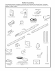
Carton inventory Your garage door opener is packaged in two cartons which contain all parts illustrated below. If anything is missing, carefully check the packing material. Parts may be "stuck" in the foam. Hardware for assembly and installation is shown on page 7.
Separate all hardware from the packages in the rail carton and the opener shown below, for the assembly and installation procedures.
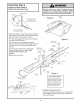
Assembly To avoid installation Assembly difficulties, Section: Pages 8 - 11 do not run the garage door opener Make sure Step 1 Assemble the T=rail & Attach the Cable Pulley Bracket bolt necks seated in the square aligned before you are tighten lock nuts. (See right and wrong views). holesandrailsare Improper assembly can cause jerky trolley operation, noise and/or nuisance door reversals. • Place the 3 T-rail sections on a flat surface for assembly. The end sections are identical.
Assembly Hardware Shown Actual Size Step 2 install the Trolley on the T-rail © * Attach the threaded shaft to the trolley with the lock washer and nuts as shown. Lock Washer 5/16" Nut 5/16"-18 Lock Washer 5/16" Outer Nut Trolley Threaded Shaft Inner Nut 5/16" Trolley Temporary Stop Screwd river * As a temporary stop, insert a screwdriver into the hole in the front end of the T-rail. \ , Slide the trolley assembly along the rail to the screwdriver stop.
Assembly Step 4 Install the Chain/Cable & Attach the Sprocket Cover Dispensing Serious injury can result if fingers become entangled in moving opener sprocket. Attach sprocket cover securely. Never operate opener while your hand is near the opener sprocket. Carton Opener Figure Leave Chain and Cable Inside Dispensing Carton to Prevent Kinking.
Assembly Step 5 Tighten the Chain & Cable Lock Washer Outer Nut • Spin the inner nut and lock washer down the threaded shaft, away from the trolley. Inner Nut "\ • To tighten the chain, turn outer nut in the direction shown. As you turn the nut, keep the chain from twisting. // ................. i' • When the chain is approximately 1/2" above the base of the T-rail at its midpoint, re-tighten the inner nut to secure the adjustment. ................
installation installation Determine Section: Pages 12- Step 1 Header Bracket Location If the header bracket is not rigidly fastened to a structural support on the header wall or ceiling, the safety reverse system may not work properly (see page 30). The door might not reverse when required, and could cause serious injury or death. Installation procedures vary according to garage door types. Follow the instructions which apply to your door.
Read the Safety instructions on page 12. They also apply to doors without tracks. Header Wall VerticaI Centerline 2x4 * Close the door and mark the inside vertical centerline of your garage door. Extend the line onto the header wall above door. If headroom clearance is minimal, you can install the header bracket on the ceiling. See page 14.
Youcanattach the header bracket either to the wall above the garage door, or to the ceiling, Follow the instructions which will work best for your particular requirements. Fasten the Header Bracket • Center the bracket on the vertical guideline with the bottom edge of the bracket on the horizontal line as shown (with the arrow pointing toward the ceiling), * Mark either set of bracket holes (do not use the holes designated for ceiling mount).
installation Step 3 Attach the T=rai! to the Header --Header Bracket • Position the opener on the garage floor below the header bracket. Use packing material as a protective base. Wall if the door spring is in the way you'll need help. Have someone hold the opener securely on a temporary support to allow the T-rail to clear the spring. Header Bracket Cable Pulley Bracket • Position the cable pulley bracket against the header bracket. • Align the bracket holes and join with a clevis pin as shown.
installation Position Step 4 the Opener Follow instructions type as illustrated. which apply to your door A 2×4 laid fiat is convenient for setting an ideal door-to-T=rail distance. 2x4 Laid Flat • Raise the opener onto a stepladder. You will need help at this point if the ladder is not tail enough. •Open the door all the way and place a 2x4 laid flat on the top section beneath the T-rail.
installation Step 5 Hang the Opener Two representative installations are shown. Yours may be different. Hanging brackets should be angled, Figure 1, to provide rigid support. On finished ceilings, Figure 2, attach a sturdy metal bracket to structural supports before installing the opener. The bracket and fastening hardware are not supplied. See accessory page 38. Figure 1 Measure the distance from each side of the opener to the structural support.
installation Install Step 6 the Premium Control Console Do not connect to live electrical wiring. Connect only to 24 Volt low voltage wires. Connection to live wires or higher voltage may cause serious injury from shock, burn or electrocution. Children operating or playing with a garage door opener can injure themselves or others. The garage door could close and cause serious injury or death.
6.AttachtheUserSafetyInstruction labeltothewall nearthedoorcontrol,andtheMaintenance Instruction labelina prominent locationonthe insideof thegaragedoor. Page32explainshowto usethe doorcontrol. Installation Step 7 Do NOT connect the power and operate the opener at this time. The trolley will travel to the full open position but will not return to the close position until the sensor beam is connected and properly aligned. See Safety Reversing Sensor instructions beginning on page 21.
installation Electrical Step 9 Requirements To prevent electrocution or fire, installation and wiring must be in compliance with local electrical and building codes. Do NOT use an extension cord, 2-wire adapter, or change the plug in any way to make it fit your outlet. To reduce the risk of electric shock, your garage door opener has a grounding type plug with a third grounding pin. This plug will onlyfit into a grounding type outlet.
The Safety Reversing System Information you'll need before you begin the installation The safety reversing sensor must be connected and aligned correctly before the garage door opener will move in the down direction. This is a required safety device and cannot be disabled. of the safety reversing sensor. Without a properly working safety reversing sensor, persons (particularly children) could be injured or killed by a closing garage door. Read and follow all instructions.
installation Step 10 I install the Safety Reversing Sensor Figure Figures 2 and 3 show assembly of brackets and "C" wrap based on the recommended installation of the sensors as shown on page 21. 2 Mounting Bracket With Square Holes .J However, Figures 4 and 5 are variations which may fit your installation requirements better. Make sure the wraps and brackets are aligned so the sensors will face each other across the garage door.
* Center each sensor unit in a "C" wrap with lenses pointing toward each other across the door (see Figure 6). Figure 6 Indicator Light Secure sensors with the hardware shown. Finger tighten the wing nut on the receiving eye to allow for final adjustment. Securely tighten the sending eye wing nut. 1/4-20 x 1-1/2" Hex Bolt , Run the wires from both sensors to the opener. Use insulated staples to secure wire to wall and ceiling. Trouble Shooting 1.
installation Step 11 Fasten Door Bracket To prevent damage to steel, aluminum, fiberglass or glass panel doors, always reinforce the inside of the door both vertically and horizontally with an angle iron. Follow instructions which apply to your door type as illustrated below or on page 25. A horizontal brace should be long enough to be secured to 2 vertical cover the height of the top panel. supports. A vertical brace should The illustration shows one piece of angle iron as the horizontal brace.
Please read and comply They apply to one-piece with the warnings doors also. Header Walt -- Finished and reinforcement instructions on page 24.
installation Connect Step 12 Door Arm to Trolley Follow instructions which apply to your door type as illustrated below and on page 27. Make sure garage door is fully closed. Pull the emergency release handle to disconnect the outer trolley from the inner trolley. Slide the outer trolley back (away from the door) about 2" as shown in Figures 1, 2 and 3. Figure 1 : Figure 2: Fasten straight door arm section to outer trolley with the the 5/16"x1" clevis pin. Secure the connection with a ring fastener.
Assemblethe DoorArm: • Fastenthestraightandcurveddoorarmsections togethertothelongest possible length, with a 2 or 3 Door Ring Bracket __ Fastener Lock Washers ___ hole overlap. • With the door closed, connect the straight door arm section to the door bracket with the 5-16" x 1-1/4" clevis pin. Clevis Pin 5/16"x1-1/4" Straight -_- Arm__//_ Screws 5/16"-18x7/8 • Secure with a ring fastener. _"_;_ /',a_ Nuts 5/16-18 _'_{_ .,.
Adjustment Adjustment Adjust Section: Pages 28 - 30 Step 1 the UP and DOWN Limits Do not make any limit adjustments until the safety reversing sensors are completely installed. Improper adjustment of the travel limits will interfere with the proper operation of the safety reverse system. The door might not reverse properly when required and could seriously injure or kill someone under it. Test the safety reverse system following all adjustments to the travel limits. See page 30.
Adjustment Adjust Step 2 I the Force Too much force on the door will interfere with the proper operation of the safety reverse system. The door might not reverse properly when required and could seriously injure or kill someone under it. Do not increase the force beyond the minimum amount required to close the door. Do not use the force adjustments to compensate for a binding or sticking garage door. Test the safety reverse system following all adjustments to force levels. See page 30.
Adjustment Step 3 Test The Safety Reversing Sensor Without a properly working safety reversing sensor, persons (particularly children) could be seriously injured or killed if trapped by a closing garage door. Repeat this test once a month. • Press the remote control push button to open the door. • Place the opener carton in the path of the door. • Press the remote control push button to close the door. The door will not move more than an inch, and the opener light(s) will flash.
iMPORTANT SAFETY iNSTRUCTiONS To reduce the risk of severe injury or death to persons: 1. READ AND FOLLOW ALL iNSTRUCTiONS. 5. if possible, use the emergency release only when the door is in a closed position. Caution should be taken whenever the disconnect cord is actuated with the door open. Weak or broken springs may cause the door to fail rapidly, causing injury or death to persons. 6. KEEP GARAGE DOORS PROPERLY BALANCED. See page 3.
Operation Activate of Your Opener the opener with any of the following: • The Remote Control: Hold push button down until the door starts to move. • The Door Control: Hold push button down until the door starts to move.
Receiver and Remote Control Programming To comply with FCC rules, adjustment or modifications of this receiver and/or transmitter are prohibited, except for changing the code setting or replacing the battery THERE ARE NO OTHER USER SERVICEABLE PARTS. Children operating or playing with a garage door opener can injure themselves or others. The garage door could close and cause serious injury or death. Do not allow children to operate the door push button(s) or remote control(s).
Having a Problem? Situation Probable Cause and Solution The opener doesn't operate from either the Door Control or the remote control: 1. Does the opener have electric power? Plug a lamp into the outlet. If it doesn't light, check the fuse box or the circuit breaker. (Some outlets are controlled by a door switch.) 2. Have you disabled all door locks? Review installation instruction warnings on Page 11. 3. Is there a build-up of ice or snow under the door? The door may be frozen to the ground.
Having Cause a Problem? (continued) Situation Probable & Solution The door opens but won't close: 1. If the opener lights blink, check the safety reversing sensor. See page 23. 2. If the opener lights do not blink and it is a new installation, check the down force. See Adjustment Step 2, page 29. For an existing installation, see below. Repeat the safety reverse test after the adjustment The door reverses for no apparent reason and opener fights don't blink: is complete. 1.
Repair Parts Rail Assembly__Parts _ 5 4 J_i 3 J 47 1 2 3 1A995 41A3489 1B3117 Master link kit Complete trolley assembly T-rail - center section 4 183Bl10 T-rail- end section 5 6 41B2616 41A3473 Cable Chain pulley bracket and cable 7 83A4 Rail grease assembly NOT SHOWN 41A3534 Installation Rail assembly hardware kit (includes hardware illustrated page 7). Parts 8 -. 2 3 \ 9 1 KEY NO, I 2 PART NO.
Repair Parts Opener Assembly PaNs I 7 D8 2O 19 18 i i,,_ I 13 15 5 17 __ 14 16 I Brown Wire (Down) Contact _/'1_ LIMIT SWITCH ASSEMBLY Drive_ Gear KEY NO. PART NO. 1 31 D380 2 41 C4220A 41A2817 4 41 B4245 5 6 41 C4253 41A4315-6D KEY NO.
Accessories Sears offers many useful accessories Sears model numbers and descriptions. for your garage door opener. They are illustrated 139.53702 Emergency Key Release: f Required for a garage with NO access door. Enables homeowner to open garage door manually from outside by disengaging trolley. 139.53703 Outdoor Key Switch: 139.53879 139.53859 8 Foot Rail Extension 139.53876 10 Foot Rail Extension: 139.53774 139.
index Access Door/Outside Key Release Accessory ............................................................................................... Chain Tension .............................................................................................................................................. Electrical 4, 5 4, 5, 11 Safety Warnings ........................................................................................................................
CRAFTSMAN° OWNER'S MANUAL GARAGE DOOR OPENER For the repair or replacement parts you need Call 7 am - 7 pm, 7 days a week 1-800-366-PART Model No. 139.53535SRTI 139.53644SRT 139.