Owner’s Manual/Manual Del Propietario ® 1/2 HP GARAGE DOOR OPENER ABRIDOR DE PUERTA DE COCHERA For Residential Use Only Model • 139.53930D ENGLISH ESPAÑOL Read and follow all safety rules and operating instructions before first use of this product. Leer y seguir todas las reglas de seguridad y las instrucciones de operación antes de usar este producto por primera vez. Fasten the manual near the garage door after installation. Guardar este manual cerca de la puerta de la cochera.
TABLE OF CONTENTS Introduction 2-7 Adjustment Safety symbol and signal word review . . . . . . . . . . . . .2 Preparing your garage door . . . . . . . . . . . . . . . . . . . . . .3 Tools needed . . . . . . . . . . . . . . . . . . . . . . . . . . . . . . . . .3 Planning . . . . . . . . . . . . . . . . . . . . . . . . . . . . . . . . . . .4-5 Carton inventory . . . . . . . . . . . . . . . . . . . . . . . . . . . . . .6 Hardware inventory . . . . . . . . . . . . . . . . . . . . . . . . . . . .
Preparing your garage door WARNING Before you begin: • Disable locks. • Remove any ropes connected to garage door. • Complete the following test to make sure your garage door is balanced and is not sticking or binding: 1. Lift the door about halfway as shown. Release the door. If balanced, it should stay in place, supported entirely by its springs. 2. Raise and lower the door to see if there is any binding or sticking.
Planning Identify the type and height of your garage door. Survey your garage area to see if any of the conditions below apply to your installation. Additional materials may be required. You may find it helpful to refer back to this page and the accompanying illustrations as you proceed with the installation of your opener. Depending on your requirements, there are several installation steps which may call for materials or hardware not included in the carton.
Planning (Continued) WARNING ONE-PIECE DOOR INSTALLATIONS • Generally, a one-piece door does not require reinforcement. If your door is lightweight, refer to the information relating to sectional doors in Installation Step 11. • Depending on your door’s construction, you may need additional mounting hardware for the door bracket (Step 11). Without a properly working safety reversal system, persons (particularly small children) could be SERIOUSLY INJURED or KILLED by a closing garage door.
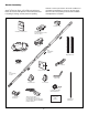
Carton Inventory Your garage door opener is packaged in one carton which contains the motor unit and all parts illustrated below. Accessories will depend on the model purchased. If anything is missing, carefully check the packing material. Parts may be stuck in the foam. Hardware for assembly and installation is shown on the next page. Save the carton and packing material until installation and adjustment is complete.
Hardware Inventory Separate all hardware and group as shown below for the assembly and installation procedures.
WARNING CAUTION ASSEMBLY STEP 1 Assemble the Rail & Install the Trolley To prevent INJURY from pinching, keep hands and fingers away from the joints while assembling the rail. To avoid installation difficulties, do not run the garage door opener until instructed to do so. The front rail has a cut out “window” at the door end (see illustration). The hole above this window is larger on the top of the rail than on the bottom. A smaller hole 3-1/2" (8.9 cm) away is close to the rail edge.
WARNING ASSEMBLY STEP 2 CAUTION Fasten the Rail to the Motor Unit To avoid SERIOUS damage to garage door opener, use ONLY those bolts/fasteners mounted in the top of the opener. • Insert a 1/4"-20x1-3/4 bolt into the cover protection bolt hole on the back end of the rail as shown. Tighten securely with a 1/4"-20 lock nut. Do NOT overtighten. • Remove the two bolts from the top of the motor unit. • Place the “U” bracket, flat side down onto the motor unit and align the bracket hole with the bolt holes.
WARNING ASSEMBLY STEP 4 Install the Chain/Cable To avoid possible SERIOUS INJURY to fingers from moving garage door opener: • ALWAYS keep hand clear of sprocket while operating opener. • Securely attach chain spreader BEFORE operating. CAUTION 1. Pull the cable around the idler pulley and toward the trolley. 2. Connect the cable to the retaining slot on the trolley, as shown (Figure 1): • From below, push pins of master link bar up through cable link and trolley slot.
ASSEMBLY STEP 5 Tighten the Chain Figure 1 • Spin the inner nut and lock washer down the trolley threaded shaft, away from the trolley. • To tighten the chain, turn outer nut in the direction shown (Figure 1). • When the chain is approximately 1/4" (6 mm) above the base of the rail at its midpoint, re-tighten the inner nut to secure the adjustment. Sprocket noise can result if chain is too loose. When installation is complete, you may notice some chain droop with the door closed. This is normal.
INSTALLATION STEP 1 Unfinished Ceiling OPTIONAL CEILING MOUNT FOR HEADER BRACKET Determine the Header Bracket Location WARNING WARNING 2x4 Header Wall Vertical Centerline of Garage Door To prevent possible SERIOUS INJURY or DEATH: • Header bracket MUST be RIGIDLY fastened to structural support on header wall or ceiling, otherwise garage door might not reverse when required. DO NOT install header bracket over drywall. • Concrete anchors MUST be used if mounting header bracket or 2x4 into masonry.
INSTALLATION STEP 2 Wall Mount Install the Header Bracket You can attach the header bracket either to the wall above the garage door, or to the ceiling. Follow the instructions which will work best for your particular requirements. Do not install the header bracket over drywall. If installing into masonry, use concrete anchors (not provided).
INSTALLATION STEP 3 Attach the Rail to the Header Bracket NOTE: (Optional) With some existing installations, you may re-use the old header bracket with the two plastic spacers included in the hardware bag. Place the spacers inside the bracket on each side of the rail, as illustrated. • Position the opener on the garage floor below the header bracket. Use packing material as a protective base. NOTE: If the door spring is in the way you’ll need help.
WARNING CAUTION INSTALLATION STEP 4 Position the Opener To prevent damage to garage door, rest garage door opener rail on 2x4 placed on top section of door. Follow instructions which apply to your door type as illustrated. SECTIONAL DOOR OR ONE-PIECE DOOR WITH TRACK A 2x4 laid flat is convenient for setting an ideal door-to-rail distance. • Remove foam packaging. • Raise the opener onto a stepladder. You will need help at this point if the ladder is not tall enough.
WARNING INSTALLATION STEP 5 Hang the Opener To avoid possible SERIOUS INJURY from a falling garage door opener, fasten it SECURELY to structural supports of the garage. Concrete anchors MUST be used if installing any brackets into masonry. CAUTION Three representative installations are shown. Yours may be different. Hanging brackets should be angled (Figure 1) to provide rigid support.
WARNING WARNING INSTALLATION CAUTIONSTEP 6 WARNING Install the Door Control To prevent possible SERIOUS INJURY or DEATH from electrocution: Locate door control within sight of door, at a minimum • Be sure power is not connected BEFORE installing door height of 5 feet (1.5 m) where small children cannot reach, control. away from moving parts of door and door hardware. If installing into drywall, drill 5/32" holes and use the • Connect ONLY to 24 VOLT low voltage wires. anchors provided.
WARNING CAUTION INSTALLATION STEP 7 Install the Light To prevent possible OVERHEATING of the endpanel or light socket, • DO NOT use short neck or specialty light bulbs. • DO NOT use halogen bulbs. Use ONLY incandescent. To prevent damage to the opener: • DO NOT use bulbs larger than 100W. • ONLY use A19 size bulbs. • Press the release tabs on both sides of lens. Gently rotate lens back and downward until the lens hinge is in the fully open position. Do not remove the lens.
INSTALLATION WARNINGSTEP 9 WARNING Electrical Requirements To prevent possible SERIOUS INJURY or DEATH from electrocution or fire: • Be sure power is not connected to the opener, and disconnect power to circuit BEFORE removing cover to establish permanent wiring connection. • Garage door installation and wiring MUST be in compliance with all local electrical and building codes. • NEVER use an extension cord, 2-wire adapter, or change plug in any way to make it fit outlet. Be sure the opener is grounded.
WARNING INSTALLATION STEP 10 Install The Protector System ® Be sure power is not connected to the garage door opener BEFORE installing the safety reversing sensor. To prevent SERIOUS INJURY or DEATH from a closing garage door: • Correctly connect and align the safety reversing sensor. This required safety device MUST NOT be disabled. • Install the safety reversing sensor so beam is NO HIGHER than 6" (15 cm) above garage floor.
INSTALLING THE BRACKETS Be sure power to the opener is disconnected. Install and align the brackets so the sensors will face each other across the garage door, with the beam no higher than 6" (15 cm) above the floor. They may be installed in one of three ways, as follows. Figure 1 DOOR TRACK MOUNT (RIGHT SIDE) Door Track Lip Garage door track installation (preferred): • Slip the curved arms over the rounded edge of each door track, with the curved arms facing the door.
MOUNTING AND WIRING THE SAFETY REVERSING SENSORS • Slide a 1/4"-20x1/2" carriage bolt head into the slot on each sensor. Use wing nuts to fasten sensors to brackets, with lenses pointing toward each other across the door. Be sure the lens is not obstructed by a bracket extension (Figure 5). • Finger tighten the wing nuts. • Run the wires from both sensors to the opener. Use insulated staples to secure wire to wall and ceiling. • Strip 7/16" (11 mm) of insulation from each set of wires.
WARNING CAUTION INSTALLATION STEP 11 Fasten the Door Bracket Fiberglass, aluminum or lightweight steel garage doors WILL REQUIRE reinforcement BEFORE installation of door bracket. Contact your door manufacturer for reinforcement kit. Follow instructions which apply to your door type as illustrated below or on the following page. A horizontal reinforcement brace should be long enough to be secured to two vertical supports. A vertical reinforcement brace should cover the height of the top panel.
ONE-PIECE DOORS Please read and comply with the warnings and reinforcement instructions on the previous page. They apply to one-piece doors also. • Center the door bracket on the top of the door, in line with the header bracket as shown. Mark either the left and right, or the top and bottom holes. • Drill 5/16" pilot holes and fasten the bracket with hardware supplied.
INSTALLATION STEP 12 Pulley Connect Door Arm to Trolley 8" (20 cm) min. Follow instructions which apply to your door type as illustrated below and on the following page. Trolley Stop Bolt SECTIONAL DOORS ONLY • Make sure garage door is fully closed. Pull the emergency release handle to disconnect the outer trolley from the inner trolley. Slide the outer trolley back (away from the pulley) about 8" (20 cm) as shown in Figures 1, 2 and 3.
ALL ONE-PIECE DOORS 1. Assemble the door arm, Figure 4: • Fasten the straight and curved door arm sections together to the longest possible length (with a 2 or 3 hole overlap). • With the door closed, connect the straight door arm section to the door bracket with the 5/16"x1-1/4" clevis pin. • Secure with a ring fastener. 2. Adjustment procedures, Figure 5: • On one-piece doors, before connecting the door arm to the trolley, the travel limits must be adjusted.
WARNING ADJUSTMENT STEP 1 Adjust the UP and DOWN Travel Limits Without a properly installed safety reversal system, persons (particularly small children) could be SERIOUSLY INJURED or KILLED by a closing garage door. • Incorrect adjustment of garage door travel limits will interfere with proper operation of safety reversal system. • If one control (force or travel limits) is adjusted, the other control may also need adjustment. • After ANY adjustments are made, the safety reversal system MUST be tested.
WARNING ADJUSTMENT STEP 2 Adjust the Force Without a properly installed safety reversal system, persons (particularly small children) could be SERIOUSLY INJURED or KILLED by a closing garage door. • Too much force on garage door will interfere with proper operation of safety reversal system. • NEVER increase force beyond minimum amount required to close garage door. • NEVER use force adjustments to compensate for a binding or sticking garage door.
WARNING ADJUSTMENT STEP 3 Test the Safety Reversal System Without a properly installed safety reversal system, persons (particularly small children) could be SERIOUSLY INJURED or KILLED by a closing garage door. • Safety reversal system MUST be tested every month. • If one control (force or travel limits) is adjusted, the other control may also need adjustment. • After ANY adjustments are made, the safety reversal system MUST be tested. Door MUST reverse on contact with 1-1/2" high (3.
WARNING OPERATION IMPORTANT SAFETY INSTRUCTIONS WARNING To reduce the risk of SEVERE INJURY or DEATH: 1. READ AND FOLLOW ALL WARNINGS AND INSTRUCTIONS. 2. ALWAYS keep remote controls out of reach of children. NEVER permit children to operate or play with garage door control push buttons or remote controls. 3. ONLY activate garage door when it can be seen clearly, it is properly adjusted, and there are no obstructions to door travel. 4. ALWAYS keep garage door in sight until completely closed.
To Open the Door Manually Using the Wall-Mounted Door Control Press the lighted push button to open or close the door. Press again to reverse the door during the closing cycle or to stop the door while it's opening. WARNING To prevent possible SERIOUS INJURY or DEATH from a falling garage door: • If possible, use emergency release handle to disengage trolley ONLY when garage door is CLOSED. Weak or broken springs or unbalanced door could result in an open door falling rapidly and/or unexpectedly.
THE REMOTE CONTROL BATTERY CARE OF YOUR GARAGE DOOR OPENER WARNING FORCE CONTROLS LIMIT AND FORCE ADJUSTMENTS: Weather conditions may cause some minor changes in door operation requiring some readjustments, particularly during LIMIT CONTROLS the first year of operation. Pages 27 and 28 refer to the limit and force adjustments. Only a screwdriver is required. Follow the instructions carefully. Repeat the safety reverse test (Adjustment Step 3, page 29) after any adjustment of limits or force.
HAVING A PROBLEM? 1. My door will not close and the light bulbs blink on my motor unit: The safety reversing sensor must be connected and aligned correctly before the garage door opener will move in the down direction. • Verify the safety sensors are properly installed, aligned and free of any obstructions. Refer to Installation Step 10: Install The Protector System®. • Check diagnostic LED for flashes on the motor unit then refer to the Diagnostic Chart on the following page.
Bell Wire Installed Safety Reversing Sensor Diagnostics Located On Motor Unit LED or Diagnostic LED Safety Sensor Safety Reversing Sensor "Learn" Button Your garage door opener is programmed with self-diagnostic capabilities. The “Learn” button/diagnostic LED will flash a number of times then pause signifying it has found a potential issue. Consult Diagnostic Chart below. Diagnostic Chart 1 FLASH Safety reversing sensors wire open (broken or disconnected).
PROGRAMMING NOTICE: If this Security✚® garage door opener is operated with a non-rolling code transmitter, the technical measure in the receiver of the garage door opener, which provides security against code-theft devices, will be circumvented. The owner of the copyright in the garage door opener does not authorize the purchaser or supplier of the non-rolling code transmitter to circumvent that technical measure.
To Add, Reprogram or Change a Keyless Entry PIN NOTE: Your new Keyless Entry must be programmed to operate your garage door opener. USING THE “LEARN” BUTTON To set a temporary PIN You may authorize access by visitors or service people with a temporary 4-digit PIN. After a programmed number of hours or number of accesses, this temporary PIN expires and will no longer open the door. It can be used to close the door even after it has expired. To set a temporary PIN: 1.
REPAIR PARTS Rail Assembly Parts 2 1 3 4 5 6 KEY NO. PART NO. 1 2 3 4 5 6 4A1008 41C5141-1 41A5665-2 144C56 41A5807 12D598-1 183A163 DESCRIPTION Master link kit Complete trolley assembly Complete rail Idler pulley Chain and cable “U” bracket NOT SHOWN Wear pads Installation Parts KEY PART NO. NO.
Motor Unit Assembly Parts 1 2 18 3 6 7 4 19 8 10 17 9 15 5 16 13 Brown Wire (Down) Contact LIMIT SWITCH ASSEMBLY 11 14 DN UP Drive Gear Center Limit Contact (Up) Contact Grey Wire Yellow Wire KEY NO. PART NO.
ACCESSORIES 139.53702 Emergency Key Release: Required for a garage with NO access door. Enables homeowner to open garage door manually from outside by disengaging trolley. 139.53726 8 Foot (2.4 m)Rail Extension To allow an 8 (2.4 m) foot door to open fully. 139.53727 10 Foot (3 m) Rail Extension: To allow a 10 (3 m) foot door to open fully. 139.53589 Support Brackets: For finished ceilings or where additional support is required, based on garage construction. Includes brackets and fastening hardware.
CONTENIDO Introducción 2-7 Ajustes 27-29 Revisión de los símbolos y términos de seguridad .........2 Preparación de la puerta de su cochera .........................3 Herramientas necesarias .................................................3 Planificación .................................................................4-5 Inventario de la caja de cartón ........................................6 Inventario de piezas.........................................................
Preparación de la puerta de su cochera ADVERTENCIA Antes de comenzar: • Quite los seguros. • Retire cualquier cuerda o cable que esté conectadoa la puerta. • Haga la siguiente prueba con su puerta para verificar que esté balanceada y que no se atore ni se pandee: 1. Levante la puerta hasta la mitad de su recorrido como se muestra. Suelte la puerta. Si está balanceada, deberá mantenerse en esa posición con sólo el soporte de los resortes. 2.
Planificación Identifique la altura y el tipo de su puerta de cochera. Revise el área de su cochera y observe si alguna de las siguientes instalaciones corresponden a la suya. A veces se requieren materiales adicionales, así que tal vez sea conveniente tener esta hoja y las ilustraciones correspondientes a mano cuando inicie la instalación de su abridor.
Planificación (continúa) ADVERTENCIA INSTALACIÓN CON PUERTAS DE UNA SOLA PIEZA • Generalmente una puerta de una sola pieza no requiere refuerzos adicionales. Si usted tiene una puerta de material liviano y quiere reforzarla, consulte la información respecto a puertas seccionales, contenida en Instalación, Paso 11. • Dependiendo del diseño de su puerta, tal vez necesite piezas de montaje adicionales para la ménsula de la puerta (Paso 11).
Inventario de la Caja de Cartón Su abridor viene empacado en una caja de cartón que contiene el motor y las piezas que se muestran en la siguiente ilustración. Tome nota de que los accesorios dependerán del modelo que haya comprado. Si falta alguna pieza, revise con cuidado el material de empaque ya que en ocasiones las piezas se atoran en el mismo. Toda la tornillería y las piezas necesarias para el montaje e instalación de su puerta se ilustran en la siguiente página.
Inventario de Piezas Antes de la instalación, organice todas las piezas en grupos como se muestra en la siguiente ilustración. TORNILLERÍA Y PIEZAS PARA EL MONTAJE Tuerca de 1/4-20 (2) Arandela de 3/8 pulg. (1) Tuerca de 3/8 pulg. (1) Perno de 1/4-20x1-3/4 pulg. (2) Enlace maestro (2) Perno loco (1) Flecha roscada del trole (1) TORNILLERÍA Y PIEZAS PARA LA INSTALACIÓN Perno de coche de 1/4-20x1/2 pulg. (2) Tuerca de mariposa 1/4-20 pulg. (2) Tornillo de cabeza cuadrada de 5/16-9x1-5/8 de pulg.
MONTAJE, PASO 1 PRECAUCIÓN PRECAUCI Monte el Riel e instale el Trole Para evitar QUE SE PELLIZQUE, conserve los manos y dedos lejos de las juntas cuando monte el reil. No encienda ni use el abridor hasta que llegue al paso de la instalación correspondiente, de otra manera corre el riesgo de complicar el proceso de instalación. El riel delantero tiene una “ventana” cortada en el extremo de la puerta (vea la ilustración).
PRECAUCIÓN PRECAUCI MONTAJE, PASO 2 Fije el Riel a la Unidad del Motor Use SÓLO el perno y la tuerca que vienen montados en la parte superior del abridor para evitar que el abridor de la puerta de cochera se dañe SERIAMENTE. • Coloque un perno de 1/4-20x1-3/4 de pulg. dentro del orificio de la cubierta de protección que se encuentra en el extremo posterior del riel, como se indica en la ilustración. Apriete bien el perno con tuerca de 1/4-20 de pulg. NO ajuste demasiado la tuerca.
ADVERTENCIA MONTAJE, PASO 4 Instale la Cadena y Cable Para evitar posibles LESIONES GRAVES en los dedos causadas por las partes móviles del abridor de puerta de cochera: • SIEMPRE mantenga las manos lejos de la rueda dentada mientras esté funcionando el abridor. • Fije bien el desplegador de cadena ANTES de operar el abridor. 1. Jale el cable alrededor de la polea loca y hacia el trole. 2.
MONTAJE, PASO 5 Apriete la Cadena Figura 1 • Gire la tuerca interna y ajuste la arandela; baje ambas por el eje roscado del trole, alejándolas del trole. • Para apretar la cadena, gire la tuerca externa en la dirección que se indica (Figura 1). • Una vez que la cadena esté aproximadamente a 6 mm (1/4 de pulg.) por encima de la base del riel en su punto medio, vuelva a apretar la tuerca interna para asegurar el ajuste. Si la cadena queda demasiado floja la rueda dentada puede hacer ruido.
INSTALACIÓN, PASO 1 INSTALACIÓN OPCIONAL DE LA MÉNSULA DEL CABEZAL EN EL CIELO RASO Determine dónde va a instalar la Ménsula del Cabezal Cielo raso sin acabado ADVERTENCIA Para evitar una posible LESIÓN GRAVE o INCLUSO LA MUERTE: • La ménsula del cabezal DEBE quedar RÍGIDAMENTE sujeta al soporte estructural en la pared delantera o en el cielo raso, de no ser así es posible que la puerta de la cochera no retroceda cuando se requiera. NO instale la ménsula del cabezal en muros falsos.
Montaje en la pared INSTALACIÓN, PASO 2 Instale la Ménsula del Cabezal UP La ménsula del cabezal se puede fijar a la pared justo por encima de la puerta de la cochera o en el cielo raso. Siga las instrucciones que sean más adecuadas para su cochera. No instale la ménsula del cabezal en un muro falso. Si va a fijar la ménsula del cabezal a ladrillo o mampostería, asegúrese de utilizar sujetadores de cemento (no se incluyen).
INSTALACIÓN, PASO 3 Coloque el Riel en la Ménsula del Cabezal NOTA: (Opcional) Con algunas instalaciones anteriores puede reutilizar la antigua ménsula del cabezal con los dos espaciadores de plástico que se incluyen en la bolsa de componentes. Coloque los espaciadores en el interior de la ménsula, a cada lado del riel, tal y como se muestra en la ilustración. • Coloque el abridor sobre el piso de la cochera debajo de la ménsula del cabezal. Use el material de empaque como base para protegerlo.
PRECAUCIÓN PRECAUCI INSTALACIÓN, PASO 4 Coloque el Abridor en Posición Para evitar que la puerta de cochera sufra daños, apoye el riel del abridor de la misma sobre un pedazo de madera de 5x10 cm (2x4 pulg.) colocado en la sección superior de la puerta. Siga las instrucciones correspondientes al tipo de puerta de su cochera, como se muestra en la ilustración. PUERTA SECCIONAL O PUERTA DE UNA SOLA PIEZA CON CARRIL Un pedazo de madera de 5x10 cm (2x4 pulg.
ADVERTENCIA INSTALACIÓN, PASO 5 Cuelgue el Abridor Para evitar la posibilidad de una LESIÓN GRAVE si se cae el abridor de la puerta de cochera, sujételo FIRMEMENTE a los soportes estructurales de la cochera. Se DEBEN usar sujetadores para concreto si alguna de las ménsulas se va a instalar en mampostería. Aquí se muestran tres ejemplos distintos para la instalación; sin embargo, es posible que su cochera no concuerde con ninguno de ellos.
ADVERTENCIA ADVERTENCIA ADVERTENCIA INSTALACIÓN, PASO 6 Instale la Unidad de Control de la Puerta Para evitar la posibilidad de una LESIÓN GRAVE o INCLUSO LA MUERTE por electrocución: • ANTES de instalar el control de la puerta, cerciórese de que la energía eléctrica no esté conectada. • Conecte el control SÓLO a cables de bajo voltaje de 24 VOLTIOS.
PRECAUCIÓN PRECAUCI INSTALACIÓN, PASO 7 Instale la Luz Para evitar un posible SOBRECALENTAMIENTO del portabombillas: • NO utilice bombillas de cuello corto ni de tipo especial. • NO utilice bombillas halógenas. Utilice SÓLO bombillas incandescentes. Para evitar daño al abridor: • NO utilice bombillas más grande que 100W. • SÓLO utilice bombillas de tamaño A19. • Oprima las lengüetas de liberación a ambos lados de la lente.
INSTALACIÓN, PASOADVERTENCIA 9 Requisitos para la Instalación Eléctrica Para evitar la posibilidad de una LESIÓN GRAVE o INCLUSO LA MUERTE por electrocución o incendio: • Cerciórese de que el abridor no esté conectado a la energía eléctrica, y desconecte la alimentación eléctrica al circuito ANTES de quitar la cubierta para establecer la conexión del cableado permanente. • Tanto la instalación como el cableado de la puerta de cochera DEBEN cumplir con todos los códigos locales de construcción y eléctricos.
ADVERTENCIA INSTALACIÓN, PASO 10 Instale La Sistema de Protección Cerciórese de que la energía eléctrica no esté conectada al abridor de la puerta de la cochera ANTES de instalar el sensor del sistema de retroceso de seguridad. Para evitar una LESIÓN GRAVE o INCLUSO LA MUERTE cuando la puerta de la cochera se está cerrando: • Conecte y alinee correctamente el sensor del sistema de retroceso de seguridad. Este dispositivo de seguridad es necesario y NO SE DEBE desactivar.
INSTALACIÓN DE LAS MÉNSULAS Asegúrese de que el abridor no esté conectado a la corriente eléctrica. Instale y alinee las ménsulas de manera que los sensores estén uno frente al otro en los lados opuestos de la puerta, a una distancia máxima de 15 cm (6 pulg.) del piso.
MONTAJE Y CABLEADO DE LOS SENSORES DEL SISTEMA DE RETROCESO DE SEGURIDAD • Deslice la cabeza de un perno de coche de 1/4-20x1/2 de pulgada dentro de la ranura de los sensores. Use tuercas de mariposa para sujetar los sensores a las ménsulas, con las lentes de cada sensor frente a frente a ambos lados de la puerta. Cerciórese de que la extensión de la ménsula no obstruya las lentes (Figura 5). • Apriete las tuercas de mariposa a mano. • Lleve los cables de los dos sensores al abridor.
PRECAUCIÓN PRECAUCI INSTALACIÓN, PASO 11 Fije la Ménsula de la Puerta En el caso de puertas de fibra de vidrio, aluminio o acero ligero, ES NECESARIO colocar un refuerzo ANTES de instalar el marco de la puerta. Póngase en contacto con el fabricante de su puerta para obtener un kit de refuerzo. Siga las instrucciones que correspondan al tipo de puerta de cochera que usted tenga, como se muestra en la ilustración o en la página siguiente.
PUERTAS DE UNA SOLA PIEZA Lea y respete todas las advertencias e instrucciones respecto a los refuerzos, contenidas en la página anterior, Instalación de puertas seccionales, ya que todos los refuerzos para su puerta de una sola pieza son los mismos. • Coloque la ménsula de la puerta en el centro de la parte superior de la misma, alineada con la ménsula del cabezal, según se indica en la ilustración. Marque ya sea los orificios derecho e izquierdo o superior y inferior.
INSTALACIÓN, PASO 12 Polea Lo menos 20 cm (8 pulg.) Conecte el Brazo de la Puerta al Trole Siga las instrucciones que correspondan al tipo de puerta de cochera que usted tenga, como se muestra a continuación y en la página siguiente. Perno de tope del trole Trole exterior Trole interior Anillo sujetador SÓLO PARA PUERTAS SECCIONALES • Cerciórese de que la puerta de la cochera esté completamente cerrada. Tire de la manija de emergencia para desconectar el trole exterior del trole interior.
TODAS LAS PUERTAS DE UNA SOLA PIEZA Ménsula de la puerta Anillo sujetador 1. Arme el brazo de la puerta, Figura 4: • Sujete las dos secciones de los brazos de la puerta (recto y curvo) a la mayor distancia posible, de manera que dos o tres de los orificios se sobrepongan uno al otro. • Cierre la puerta y fije la sección recta del brazo a la ménsula de la puerta con el pasador de chaveta de 5/16x1-1/4 de pulgada. • Asegúrelos con un anillo sujetador. Arandela de 5/16 de pulg.
ADVERTENCIA AJUSTES, PASO 1 Ajuste el Límite del Recorrido HACIA ARRIBA y HACIA ABAJO Al ajustar el límite del recorrido de la puerta, se regula hasta qué punto ésta se detendrá al abrir y al cerrar. Para poner en marcha el abridor, oprima el botón de control de la puerta. Haga funcionar el abridor durante un ciclo completo del recorrido.
ADVERTENCIA AJUSTES, PASO 2 Ajuste la Fuerza Si el sistema de retroceso de seguridad no se ha instalado debidamente, las personas (y los niños pequeños en particular) podrían sufrir LESIONES GRAVES o INCLUSO LA MUERTE cuando se cierra la puerta de la cochera. • Si el límite de la fuerza de la puerta de la cochera es excesivo interferirá con la operación adecuada del sistema de retroceso de seguridad.
ADVERTENCIA AJUSTES, PASO 3 Pruebe el Sistema de Retroceso de Seguridad Si el sistema de retroceso de seguridad no se ha instalado debidamente, las personas (y los niños pequeños en particular) podrían sufrir LESIONES GRAVES o INCLUSO LA MUERTE cuando se cierra la puerta de la cochera. • El sistema de retroceso de seguridad SE DEBE probar cada mes. • Si se ajusta uno de los controles (límites de la fuerza o del recorrido), es posible que sea necesario ajustar también el otro control.
OPERACIÓN INSTRUCCIONES IMPORTANTES DE SEGURIDAD ADVERTENCIA Para reducir el riesgo de LESIONES GRAVES o la MUERTE: 9. Si ajusta uno de los controles (límites de la fuerza o del recorrido), es posible que sea necesario ajustar también el otro control. 10. Después de llevar a cabo CUALQUIER ajuste, SE DEBE probar el sistema de retroceso de seguridad. 11. El sistema de retroceso de seguridad SE DEBE probar cada mes. La puerta DEBE retroceder al entrar en contacto con un objeto de 3.8 cm (1-1/2 de pulg.
Cómo Usar la Unidad de Control de Pared Cómo Abrir la Puerta Manualmente Oprima el botón iluminado para abrir o cerrar la puerta. Oprima de nuevo para que la puerta retroceda en el ciclo de cierre o para detener la puerta cuando se está abriendo. ADVERTENCIA A Para evitar la posibilidad de una LESIÓN GRAVE o INCLUSO LA MUERTE si la puerta de la cochera se cae: • De ser posible, use la manija de liberación de emergencia para soltar el trole SÓLO cuando la puerta de la cochera esté CERRADA.
LA BATERÍA DEL CONTROL REMOTO MANTENIMIENTO DE SU ABRIDOR DE PUERTA DE COCHERA ADVERTENCIA AJUSTES DE LÍMITE Y FUERZA: Las condiciones climatológicas CONTROLES DE FUERZA pueden ocasionar cambios menores en la operación de la puerta, los cuales van a requerir algunos reajustes, en particular KG durante el primer año de KG operación. En las páginas 27 y 28 se CONTROLES DE LÍMITE encuentra la información sobre los ajustes de límite y de fuerza. Lo único que necesita es un destornillador.
SI TIENE ALGÚN PROBLEMA 1. La puerta no cierra y las luces de la unidad del motor parpadean: El sensor del sistema de retroceso de seguridad debe estar instalado y alineado correctamente para que el sistema de apertura de la puerta de la cochera se mueva en sentido descendente. • Asegúrese de que los sensores de seguridad estén instalados y alineados correctamente, y que estén libres de obstrucciones. Consulte la sección Instalación, Paso 10: Instale La Sistema de Protección®.
Cable de campana Diagnóstico situado en unidad del motor LED o Diagnóstico LED Sensor de seguridad de reversa Sensor Botón "Aprender" Tabla de Diagnóstico 1 PARPADEO El circuito de los sensores de retroceso de seguridad está abierto (cable roto o desconectado). O BIEN 2 PARPADEOS Hay un cortocircuito en el cable de los sensores de retroceso de seguridad, o los cables blanco y negro están invertidos. 3 PARPADEOS El control de la puerta o el cable tienen un cortocircuito.
CÓMO PROGRAMAR EL ABRIDOR AVISO: Si utiliza este abre puertas de garaje Security✚® con un transmisor no dotado de un sistema de códigos de salto (código aleatorio), se verán circunvenidas las medidas técnicas incorporadas en el receptor del abridor para proteger contra los aparatos de captura de códigos.
Cómo Agregar, Reprogramar o Cambiar un Código de Entrada sin Llave NOTA: Su nueva Entrada sin llave debe programarse para que opere el abridor de la puerta de su cochera. CÓMO USAR EL BOTÓN LEARN (APRENDER) Para poner un PIN temporal Usted puede autorizar el acceso a sus visitas o a personal de servicio con un PIN temporal de cuatro dígitos. Después de un determinado número de horas programadas, o número de accesos, este PIN temporal expira y no vuelve a abrir la puerta.
ACCESORIOS 139.53702 139.53726 Liberador de la llave de emergencia: Se requiere en las cocheras que NO tienen puerta de acceso. Permite al dueño de la casa abrir la puerta de la cochera manualmente desde el exterior, desconectando el trole. Extensión del riel de 2.4 m (8 pies): Permite que una puerta de 2.4 m (8 pies) se abra completamente. 139.53753 SECURITY✚® Control remoto de 3 funciones: Incluye el clip del visor. 139.
Get it fixed, at your home or ours! Your Home For repair – in your home – of all major brand appliances, lawn and garden equipment, or heating and cooling systems, no matter who made it, no matter who sold it! For the replacement parts, accessories and owner’s manuals that you need to do-it-yourself. For Sears professional installation of home appliances and items like garage door openers and water heaters. 1-800-4-MY-HOME® (1-800-469-4663) Call anytime, day or night (U.S.A. and Canada) www.sears.