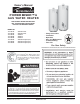
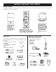
Owner’s Manual POWER MISER™ 6 GAS WATER HEATER FOR POTABLE WATER HEATING ONLY. NOT SUITABLE FOR SPACE HEATING. NOT FOR USE IN MOBILE HOMES. MODEL NO. 153.336162 153.336262 153.336362 153.336466 153.336566 153.336762 153.336862 153.336962 30 Gallon Short 40 Gallon Short 30 Gallon 40 Gallon 50 Gallon 30 Gallon Propane (L.P.) 40 Gallon Propane (L.P.) 50 Gallon Propane (L.P.
SAFE INSTALLATION, USE AND SERVICE Your safety and the safety of others is extremely important in the installation, use and servicing of this water heater. Many safety-related messages and instructions have been provided in this manual and on your own water heater to warn you and others of a potential injury hazard. Read and obey all safety messages and instructions throughout this manual.
SAFETY PRECAUTIONS 3
TABLE OF CONTENTS SAFE INSTALLATION, USE AND SERVICE ................................................................................................. 2 SAFETY PRECAUTIONS .............................................................................................................................. 3 TABLE OF CONTENTS ................................................................................................................................ 4 CUSTOMER RESPONSIBILITIES ....................................
CUSTOMER RESPONSIBILITIES • The installation must conform with these instructions and the local code authority having jurisdiction. In the absence of local codes, installations shall comply with the following: Thank You for purchasing a Kenmore water heater. Properly installed and maintained, it should give you years of trouble free service. If you should decide that you want the new water heater professionally installed by Sears call 1-800-4-MY-HOME®.
MATERIALS AND BASIC TOOLS NEEDED Materials Needed To simplify the installation Sears has available the installation parts shown below. You may or may not need all of these materials, depending on your type of installation. EXPANSION TANKS FOR THERMAL EXPANSION CONDITIONS AVAILABLE IN 2 GALLONS (7.6 LITERS) AND 5 GALLONS (18.9 LITERS) CAPACITY HROUGH LOCAL SEARS STORE OR SERVICE CENTER. WATER HEATER INSTALLATION KIT WITH FLEXIBLE CONNECTORS FOR 3/4” (19.05 mm) OR 1/2” (12.
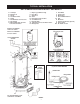
TYPICAL INSTALLATION GET TO KNOW YOUR WATER HEATER - GAS MODELS A B C D E F G H I Vent Pipe Draft Hood Anode Hot Water Outlet Outlet Flexible Water Connections Gas Supply Manual Gas Shut-off Valve Ground Joint Union J K L M N O P Q R Drip Leg (Sediment Trap) Inner Door Outer door Union Inlet Water Shut-off Valve Cold Water Inlet Inlet Dip Tube Temperature-Pressure Relief Valve Rating Plate * INSTALL IN ACCORDANCE WITH LOCAL CODES.
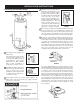
INSTALLATION INSTRUCTIONS Removing the Old Water Heater 4. Attach a hose to the water heater drain valve and put the other end in a floor drain or outdoors. Open the water heater drain valve. Open a nearby hot water faucet which will relieve pressure in the water heater and speed draining. The water passing out of the drain valve may be extremely hot. To avoid being scalded, make sure all connections are tight and that the water flow is directed away from any person, see Figures 2 and 5. FIGURE 5. 5.
• Devices that will turn off the gas supply to a gas water heater while at the same time shutting off its water supply. Facts to Consider About the Location Carefully choose an indoor location for the new water heater, because the placement is a very important consideration for the safety of the occupants in the building and for the most economical use of the appliance. This water heater is not for use in manufactured (mobile) homes or outdoor installation.
Minimum clearances between the water heater and combustible construction are 0 inch at the sides and rear, 4 inches (102 mm) at the front, and 6 inches (153 mm) from the vent pipe, see Figure 8. Clearance from the top of the jacket is 12 inches (305 mm) on most models. Note that a lesser dimension may be allowed on some models, refer to the label attached adjacent to the gas control valve on the water heater. FIGURE 9.
commence within 12 inches (30 cm) of the top and one commencing within 12 inches (30 cm) of the bottom of the enclosures. • Do not apply insulation to the top of the water heater, as this will interfere with safe operation of the draft hood. • Do not cover the outer door, thermostat or temperature & pressure relief valve. • Do not allow insulation to come within 2” (50.8 mm) of the floor to prevent blockage of combustion air flow to the burner. • Do not cover the instruction manual.
Water Piping FIGURE 12. HOTTER WATER CAN SCALD: Water heaters are intended to produce hot water. Water heated to a temperature which will satisfy space heating, clothes washing, dish washing, cleaning and other sanitizing needs can scald and permanently injure you upon contact. Some people are more likely to be permanently injured by hot water than others. These include the elderly, children, the infirm, or physically/mentally handicapped.
• Look at the top of the water heater. The cold water inlet is marked “COLD”. Put two or three turns of teflon tape around the threaded end of the threaded-to-sweat coupling and around both ends of the 3/4” NPT threaded nipple. Using flexible connectors, connect the cold water pipe to the cold water inlet of the water heater. This water heater shall not be connected to any heating systems or component(s) used with a non-potable water heating appliance.
Fit T & P valve insulation over valve. Make sure that the insulation does not interfere with the lever of the T & P valve. Secure all insulation using tape. Temperature-Pressure Relief Valve FIGURE 16. This heater is provided with a properly certified combination temperature - pressure relief valve by the manufacturer.
The temperature-pressure relief valve must be manually operated at least once a year. Caution should be taken to ensure that (1) no one is in front of or around the outlet of the temperature-pressure relief valve discharge line, and (2) the water manually discharged will not cause any bodily injury or property damage because the water may be extremely hot. and mechanically actuated vent dampers).
Be sure vent pipe is properly connected to prevent escape of dangerous flue gases which could cause deadly asphyxiation. Chemical vapor corrosion of the flue and vent system may occur if air for combustion contains certain chemical vapors. Spray can propellants, cleaning solvents, refrigerator and air conditioner refrigerants, swimming pool chemicals, calcium and sodium chloride, waxes, bleach and process chemicals are typical compounds which are potentially corrosive. Gas Piping FIGURE 17.
Sediment Traps Contaminants in the gas lines may cause improper operation of the gas control valve that may result in fire or explosion. Before attaching the gas line be sure that all gas pipe is clean on the inside. To trap any dirt or foreign material in the gas supply line, a drip leg (sometimes called a sediment trap) must be incorporated in the piping. The drip leg must be readily accessible. Install in accordance with the Gas Piping section.
OPERATING INSTRUCTIONS FOR YOUR SAFETY READ BEFORE LIGHTING WARNING: If you do not follow these instructions exactly, a fire or explosion may result causing property damage, personal injury or loss of life. BEFORE OPERATING: ENTIRE SYSTEM MUST BE FILLED WITH WATER AND AIR PURGED FROM ALL LINES. A. This appliance has a pilot which is lit by a piezo electric gas ignition system. Do not open the inner door of the appliance and try to light the pilot by hand.
Temperature Regulation THE WATER HEATER SHOULD BE LOCATED IN AN AREA WHERE THE GENERAL PUBLIC DOES NOT HAVE ACCESS. IF A SUITABLE AREA IS NOT AVAILABLE, A COVER SHOULD BE INSTALLED OVER THE THERMOSTAT TO PREVENT TAMPERING. Suitable covers are available through the Sears Service Center. Due to the nature of the typical gas water heater, the water temperature in certain situations may vary up to 30F° (16.7 C°) higher or lower at the point of use such as, bathtubs, showers, sink, etc.
SERVICE AND ADJUSTMENT Tank (Sediment) Cleaning Burner Inspection Sediment build-up on the tank bottom may create varying amount of noise, and if left in the tank will cause permanent tank failure. In some water areas, you may not be able to drain all sediment deposits by simply draining the tank. In these cases Mag-Erad (part no. 23600) can be used to help remove the sediment deposits. This may be ordered from the Sears Service Center. For ordering, refer to the Parts Order List section.
Housekeeping Temperature-Pressure Relief Valve Operation Vacuum around base of water heater for dust, dirt, and lint on a regular basis. The temperature-pressure relief valve must be manually operated at least once a year.
5. Screw the handle and cap assembly back into the drain valve and retighten using a wrench. DO NOT OVER TIGHTEN. 2. CLOSE the cold water inlet valve to the water heater. 3. OPEN a nearby hot water faucet and leave open to allow for draining. 6. Follow instructions in the Filling The Water Heater section. 4. Connect a hose to the drain valve and terminate to an adequate drain. 7. Check for leaks. 5. OPEN the water heater drain valve to allow for tank draining. 8.
TROUBLESHOOTING GUIDE Start Up Conditions NOTE: Expansion tanks are pre-charged with a 40 psi air charge. If the inlet water pressure is higher than 40 psi, the expansion tank’s air pressure must be adjusted to match that pressure, but must not be higher than 80 psi. Thermal Expansion Water supply system may, because of such events as high line pressure, frequent cut-offs, and the effects of water hammer have installed devices such as pressure reducing valves, check valves, back flow preventers, etc.
is not drawn toward the draft hood, shut off water heater and make necessary air supply changes to correct. from hydrogen sulfide gas dissolved in the water. The smell is the result of four factors which must all be present for the odor to develop: Condensation • a concentration of sulfate in the supply water. Whenever the water heater is filled with cold water, some condensate will form while the burner is on. A water heater may appear to be leaking when in fact the water is condensation.
Read this manual first. Then before checking the water heater make sure the gas supply has been turned “OFF”, and never turn the gas “ON” before the tank is completely full of water. Operational Conditions (Continued) Leakage Checkpoints Never use this water heater unless it is completely filled with water. To prevent damage to the tank, the tank must be filled with water. Water must flow from the hot water faucet before turning “ON” gas to the water heater, see Figure 27. A.
TROUBLESHOOTING GUIDE (Continued) These guidelines should be used by a qualified service agent. Call Sears Service at 1-800-4-MY-HOME® (1-800-469-4663) for assistance. Inform the associate that this is a “Flammable Vapor Ignition Resistant” Product. Problem WATER LEAKS LEAKING T&P VALVE Cause Solution Improperly sealed, hot or cold supply connection, relief valve, drain valve, or thermostat threads. Leakage from other appliances or water lines. Condensation of flue products.
NOTES: 27
NOTES: 28
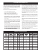
PARTS ORDER LIST POWER MISER™ 6 GAS WATER HEATER MODEL NO’S 153.336162 153.336262 153.336362 3 30 Gallon Short 40 Gallon Short 30 Gallon BURNER ASSEMBLY Model Numbers Key No.
PARTS ORDER LIST POWER MISER™ 6 GAS WATER HEATER MODEL NO’S 153.336466 153.336566 3 40 Gallon 50 Gallon BURNER ASSEMBLY Model Numbers Key No.
PARTS ORDER LIST POWER MISER™ 6 GAS WATER HEATER MODEL NO’S 153.336762 153.336862 153.336962 3 30 Gallon Propane (L.P.) 40 Gallon Propane (L.P.) 50 Gallon Propane (L.P.) BURNER ASSEMBLY Model Numbers Key No.
6 - YEAR LIMITED WARRANTY ON WATER HEATER For six years from the date of purchase, if this water heater is installed and operated in a single-family home in accordance with the owner’s manual instructions and all local applicable plumbing codes, Sears will: 1. 2. Supply free water heater parts for those that are defective in material or workmanship. Supply a free water heater for one that develops a leak.