5.5 HP 2 Stage Snow Thrower SKU #270-3250 Owner's Manual DO NOT RETURN Questions? Please call our PLEASE THROWER. READ THIS ENTIRE MANUAL BEFORE customer USING Please keep this manual available to all users during the entire life of the snow thrower. 2005 Yardworks(R). Do not reprint without written help line: M-F 84 CT Thank you for purchasing a Yardworks ®snow thrower. This manual provides information regarding the setup, operation, and maintenance of this product.
TABLE OF CONTENTS GENERAL SAFETY PROCEDURES ........................................................................ PACKAGE CONTENTS ....................................................................................... SNOW THROWER COMPONENTS ......................................................................... ENGINE COMPONENTS ...................................................................................... ASSEMBLY ............................................................................
GENERAL SAFETY PROCEDURES Pleasefamiliarizeyourselfwith the following safetysymbolsandwords: The safety alert symbol A is used with one of the safety words (DANGER, CAUTION, or WARNING) to alert you to hazards. Please pay attention to these hazard notices both in this manual and on the snow thrower. DANGER: Indicates not followed.
A WARNING: Foreign objects entering the auger or impeller can create clogs, jams, projectiles, and other dangerous conditions. • Do not use in the path of wires, doormats, snow toys, or other foreign objects. • If the snow thrower intakes a foreign object, stop the engine, wait for the auger and impeller to stop rotating, and inspect the snow thrower for damage. • Turn off the engine and make sure that all moving parts have stopped before clearing any clogs or jams.
A WARNING: In addition to the above warnings please note the following precautions that should be followed when operating this or ANY machine. • Read all manuals and warning labels before using a machine. • Never operate a machine with any guard or cover removed. • Remove all adjusting keys and wrenches before use. • Do not allow children or uninstructed persons to operate. • Use the right tool. Do not force the tool or attachment to do a job for which it was not designed.
PACKAGE CONTENTS Your snow thrower comes with the items listed below. following items are included with your snow thrower. O (888) ITEM If you are 315-3080 missing M-F components DO NOT 8-5 CT for customer Please check to see that all of the RETURN TO STORE, please call service.
SNOW THROWER COMPONENTS Please familiarize yourself with the locations and functions of the various components and controls of the snow thrower. 2 3 4 \ 5 \ 7 (internal) t0 (1) Drive Control- Drives the snow thrower at the pre-selected speed and direction when depressed. (2) Handle- Hold the snow thrower here when using. (3) Auger Control- Rotates the auger when depressed. (4) Drive Speed Control- Sets the speed and direction of the snow thrower.
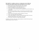
ENGINE COMPONENTS Please familiarize yourself with the locations and functions of the various components and controls of the engine portion of the snow thrower. 9 10 (1) Recoil Starter Handle- Pull-cord for starting engine. (2) Throttle Lever- Use to control engine speed. This should be set to the highest speed when using the snow thrower. (3) Fuel Valve Lever- Controls flow of fuel into the engine. (4) Choke Lever- Adjusts the amount of air let into the engine.
ASSEMBLY In order to best protect the snow thrower while in the package, this product comes with some components disassembled. Please complete the following assembly steps before proceeding to use the snow thrower. For ease of assembly, we recommend attaching the components in the order listed in this manual.
NOTE: For easiestassembly,we recommendnot attachingthelower bolt of eachhandle bracketuntil after assemblingthe chuterotationhandle,augeranddrive handlecables, anddrive speedcontrollever. Figure 2- Handle Assembly Attaching Drive Speed Control Lever To attach the drive speed control lever, slide it through the drive speed selection hole in the handle and attach it at the base of the snow thrower using two bolts and two nuts as shown in figure 3.
Chute Rotation Handle To attach the chute rotation handle: 1. Remove the handle grip from the handle by removing the screw at the end (see figure 4). 2. Slide the end of the chute rotation handle, with the grip removed, through the eye hole on the snow thrower handle as shown in figure 4 a. 3. Slide the other end of the chute rotation handle through the hole near the base of the chute. Line the spiral of the handle up with the grooves in the base of the chute (see figure 4b).. 4.
NOTE: When attaching the cables, be sure they are properly threaded through the main handle. The auger control cable should fit through the hole next to the speed selector. The drive control cable should fit in the handle groove on the other side of the speed selector.
PREPARING THE SNOW THROWER FOR USE _ The following section describes steps you must follow to prepare the snow thrower for use. If after reading this section, you are unsure about how to perform any of the steps please call (888) 315-3080 M-F 8-5 CT for customer service. Failure perform these steps properly can damage the snow thrower or shorten its life.
5. 6. Remove the oil filler cap again and inspect the attached dipstick. Oil should now be visible on the stick. Ifoil is not visible on the stick, you may need to add more oil and repeat steps 4 and 5. Replace the oil filler cap and screw tightly. NOTE: Even if you have previously measured 21 ounces ofoil, some spillage is common when adding oil to the crankcase. Always ensure that the engine has sufficient oil by checking the dipstick. See Figure 6 for proper oil level.
IMPORTANT: • Never use an oil/gasoline mixture. • Never use old gas. • Avoid getting dirt or water in the fuel tank. • Gas can age in the tank and make it hard to start up the snow thrower in the future. Never store the snow thrower for extended periods of time with fuel in the tank. Adjust Skid Shoes Adjustment of the skid shoes governs the height above the ground at which the auger shield operates.
OPERATION _ Before starting the snow thrower, make sure you have read and performed the steps in the "Preparing the Snow Thrower for Use" section of this manual. If you are unsure about how to perform 3080 Starting M-F any of the steps in this manual please call (888) 8-5 CT for customer the Snow 315- service. Thrower To start up the snow thrower, perform the following steps: 1. Turn the engine fuel valve lever to the "on" position (see figure 8). 2.
5. 6. 7. Pull on the recoil starter handle slowly until a slight resistance is felt (see figure 10) then pull quickly to start the engine. Return cord gently into the machine. Never allow the cord to snap back. If engine fails to start, repeat step 5. NOTE: After repeated attempts to start the engine, please consult the troubleshooting guide before attempting again. If problems persist please call (888) 315-3080 M-F 8-5 CT.
You can adjust the drive speed and direction using the drive speed control lever. Be sure to release both the auger control handle and the drive control handle before adjusting the drive speed control lever. As you use the snow thrower, you may want to adjust the chute outlet direction. Be sure to release both the auger control handle and the drive control handle before adjusting the chute outlet direction.
STOPPING THE SNOW THROWER When you are finished using the snow thrower, perform the following steps to shut it down: 1. Move the snow thrower away from any snow piles. 2. Run the auger and impeller for 30 seconds to clear any remaining snow inside the snow thrower. Set the engine switch to the "off' position. This will stop the motor. 4. Move the fuel valve lever to the "off' position. 5. Dust snow off of all snow thrower surfaces. .
MAINTENANCE/CARE Proper routine maintenance of the snow thrower will help prolong its life. Please perform maintenance checks and operations according the schedule in figure 14. If you have questions about any of the maintenance please call (888) 315-3080 M-F 8-5CT. procedures CAUTION: running.
Clearing Auger or Impeller Jams A WARNING: The auger and impeller rotate at fast speeds that can cause damage or even amputation to body parts. Even if you do not see the auger or impeller rotating, they may start at any time if the engine is running. • Always turn off the engine before attempting to clear any clogs or jams. • Keep hands and feet away from rotating parts while the engine is running. • Do not wear loose fitting clothing that can become entangled in rotating parts.
. that performs well in cold conditions. The telnperamre conditions and recommended oil grade will vary by geographic area. Once you have ensured the engine oil level is correct, replace the oil filler cap and screw tightly. Figure Rephtcing TIMELINE: when dirty. 16- Removing oil filler cap Figure 17- Proper oil level the Oil You should drain and replace the oil in the crankcase every 50 hours or To drain the oil from the crankcase: 1. Place a bucket near the engine to catch oil as it drains.
After you have drained the dirty oil, refill the crankcase with fresh auto motor oil. To fill the crankcase, perform the steps listed in the "Checking/Adding Oil" portion of this MAINTENANCE section. NOTE: your Never local Air Filter dispose recycling of used center motor or auto oil in the trash garage to arrange or down a drain. Please call oil disposal. Maintenance TIMELINE: Clean the air filter every 50 hours or more often in dirty environments. To clean the air filter: 1.
Spark Plug Maintenance TIMELINE: Every 100 hours or as needed. The spark plug is important for proper engine operation. A good spark plug should be intact, free of deposits, and properly gapped. To inspect your spark plug: 1. Pull on the spark plug cap to remove it. 2. Unscrew the spark plug from the engine using the spark plug wrench included with this product (see figure 20). 3. Visually inspect the spark plug. If it is cracked or chipped, discard and replace with a new spark plug.
7. 8. Replace the bolt on the carburetor. Store the emptied gasoline in a suitable place. _k CAUTION: Do not store A[k CAUTION: Never authorities to dispose pour TIMELINE: Drh,e one season down a drain to another. or in a gutter. Call your local of gas properly. Figure Adjusdng fuel from gasoline and Auger 22- Draining gas from the carburetor Cables As needed. Over time, the tension in the cables that lead to the drive control and auger control handles may loosen.
Replacing Shear Pins A WARNING: The auger and impeller rotate at fast speeds that can cause damage or even amputation to body parts. Even if you do not see the auger or impeller rotating, they may start at any time if the engine is running. • Always turn off the engine before attempting to clear any clogs or jams. • Keep hands and feet away from rotating parts while the engine is running. Do not wear loose fitting clothing that can become entangled in rotating parts.
SPECIFICATIONS Snow Thrower Clearing Width Throwing Distance 22 Inches Max. 50 feet Chute Rotation 180 degrees Wheel Pneumatic, Drive Speeds Dimensions Forward: 0.9, 1.2, 1.5, 1.8, 2.5 MPH Reverse: 0.9, 1.2 MPH L= 35.5" W = 24.5" H = 31.5" Dry Mass 158 Lbs tubeless, size 4.10-6 N.H.S. Engine Engine Type Ignition System 4-Stroke OHV Single Cylinder Non-Contact Transistor Fuel Tank Capacity Crankcase oil capacity 0.95 Gallons 21.1 Fluid Ounces TROUBLESHOOTING IMPORTANT: M-F 8-5.
Auger or impeller does not rotate _,uger drive handle s not depressed _,uger drive handle sable is loose Foreign substance slogging auger or mpeller Depress auger drive handle Adjust tension in cable Turn off machine and unclog auger or impeller Shear pin broken Replace shear pin. Belt broken or loose Call customer service Snow is not thrown or not thrown very Impeller or chute is far slogged Turn off engine and unclog. Shute deflector is set too low Adjust chute deflector angle.
9 8 r_ \ 6 79 36 / / 10 i4 100 ÷ \ \ 99 b_ \ !05 9O
SNOW THROWER PARTS Part # Part Description 1 _andle assembly 2 _uger and chive conr_ot handles 3 LIST Quantity Part # Part Description Quantity 56 8 lmll Flax washer 3 2 57 M8 x 20 Hex screws 1 _ubber cap 2 58 l"_nslmssion 1 4 _8x50 4 59 _tlley motmt1_ 5 _8 hex imts 35 60 transmission 6 Ftmlbuckte 2 61 Deep Groove Bearing 1set He..
@ @
ENGINE PART # PARTS LIST PART DESCRIPTION PART QTY 1 _LANGE BOLT ( M6'12 2 _EAD COVER 3 _tEAD COVER 4 BREATHER 5 _IVOT ADJUSTING 6 ROCKER AR_M PIVOT 7 # QTY PART DESCRIPTION 1 12 52 _'ARBURETOR COMP 1 53 _'ARBURETOR PACKING 1 54 2HOKE 1 55 2ARBURETOR SPACER 2 56 a_IR CLEANER ELBOW COMP 2 57 FLANGE NUT ( M6 ) ROCKER AK\I 2 58 FLANGE BOLT ( M6'20 8 _IVOT BOLT ( M8 ) 2 59 ELBOW GASKET 1 9 VALVE 1 60 SILENCER 1 1 61 hIR FILTER ELEMENT 1 62 adR F
1 96 E'ONTROL ASSY 1 97 £HROTTLE ENGINE STOP SWITCH ASSY 1 98 3OVERNOR ROD 1 _COIL 1 99 _O\7EI_NOR SPRING ] 3 100 .)UADRATE BOLT ( M6 ) 1 1 101 2ONTROL 45 _'LANGE BOLT ( M6'16 46 :AN COVER 47 48 49 _'LANGE BOLT ( M6'8 50 .
LIMITED WARRANTY FOR YARDWORKS _'s_ SNOW THROWER Remember to save your receipt and to accurately fill out and mail your product card. You must provide proof of purchase for all warranty work. This Yardworks workmanship ": snow thrower for a period is warranted to be free from defects of two (2) year from date of original is used for Commercial or Rental original purchase. Keep purchase in materials purchase.