
Owner`s manual


TS
SERVICE AND ADJUSTMEN
JL ..... ..... ,,,, H i m, Jll,J .....
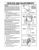
TRACK DRIVE BELT TO ADJUST THE FRICTION WHEEL
If your snow thrower will not move forward, check the
track drive belt for wear. If the track drive belt needs to
be replaced, proceed as follows:
• Disconnect the spark plug wire.
• Remove the belt cover,
• Loosen the left handbelt guide (See Fig 27) mount-
ing screw and move the belt guide away from the
bell
if the snow thrower will not move forward, you need to
check the track drive belt, the traction drive cable or the
friction wheel it the friction wheel is damaged, it will need
to be replaced_ See the To Replace Friction Wheel para-
graph on page 21. If the friction wheel is not worn, check
the adjustment, as foItows:
• Disconnect the spark plug wire_
• Drain the gasoline from the_]as tank.
• Pull the track drive idler pulley (See Fig. 27) back
and slip the belt past the idler pulley
• Remove the belt from the engine pulley.
• Remove the belt between the two large pulleys
• Install the new original equipment replacement belt
in reverse order of removal.
o
o
O
Adjust the left hand belt guide and tighten the
mounting screw (see To Adjust The Belt Guides
paragraph below).
Reinstall the belt cover.
Reconnect the spark ptug wire_
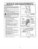
TO ADJUST THE BELT GUIDES
There are two belt guides onyour snow thrower, a left and
right After you replace a track or auger drive belt, you
need to adjust one or both of the belt guides° Proceed as
follows for each belt:
• Disconnect the spark plug wire.
• Remove the belt cover (See Fig 26)
• Engage the auger drive clutch lever,
• Measure the distance between the belt guides and
the belt (See Fig 28)° The distance shouldbe 3/32"
for each guide.
• If adjustment is necessary, loosen the belt guide
mounting bolts. Move the belt guides to the correct
position Tighten the mounting bolts
Reinstallthe belt cover.
o
o
Reconnect the spark plug wire
REM -_BI_.__I |_.BOLT
PANEL
LOOSEN BOLT,.._ LOOSEN BOLT
TRACK CONNECTING ROD
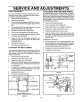
• Stand snow thrower on the auger housing end.
• Remove the bottom panel (See Fig, 29).
o Position the shifter lever in first (1) gear.
o Note the position of the friction wheel on the disc
drive plate The right side of the friction wheel should
be 3-3/8" fromthe left outer side ofthe discddve plate
(See Fig. 30)
If adjustment is necessary:
• Loosen the jam nut "A" on the speed select rod Re-
move the ball joint from the shifter bracket Lengthen
or shorten the rod by turning the adaptor to obtain the
correct friction wheel position (See Fig. 31)
• Reinstall the ball joint and tighten the jam nut.
• Reinstall the bottom panel
FRICTION
WHEEL
3-3/8
INCH
DRIVE
PLATE
FIG. 30
SPEEDSELECTROD
- JAM NUT
IFTER
BRACKET
ADAPTOR,
BALL
I
t
FIG. 29
FIG. 31
2O