CRAFTSMAN® OWNER'S MANUAL 10 HORSEPOWER 29" DUAL STAGE 120V. ELECTRIC START SNOW THROWER WHEN ORDERING MODEL NO. 536.886331 REPAIR PARTS, ALWAYS Each SNOW THROWER has its own MODEL NUMBER found on the engine mount frame. Each ENGINE has its own MODEL found on the BLOWER HOUSING. NUMBER Always mention these MODEL NUMBERS when requesting service or Repair Parts for your SNOW THROWER.
SAFETY & RULES CAUTION: ALWAYS DISCONNECT SPARK PLUG WIRE AND PLACE WIRE WHERE IT CANNOT CONTACT SPARK PLUG TO PREVENT ACCIDENTAL STARTING WHEN SETTING-UP TRANSPORTING, ADJUSTING OR MAKING REPAIRS. A IMPORTANT SAFETY STANDARDS REQUIRE OPERATOR PRESENCE CONTROLS TO MINIMIZE THE RISK OF INJURY. YOUR SNOW THROWER IS EQUIPPED WITH SUCH CONTROLS. DO NOT ATTEMPT TO DEFEAT THE FUNCTION OF THE OPERATOR PRESENCE CONTROL UNDER ANY CIRCUMSTANCES.
SAFETY RULES • • • Never operate the snow thrower near glass enclosures, automobiles, window wells dropoffs, and the like without proper adjustment of the snow discharge angle. Keep children and • Thoroughly Never operate the snow thrower at high transport speeds on slippery surfaces. Look behind and use care when backing. damage, and repair the damage before restarting and operating the snow thrower.
CONGRATULATIONS on your purchase of a Sears _rattsman Snow Thrower. It has been designed, engineered a_d manufactured to give you the best poss;ble dependability and performance. Should you experience any problem you cannot easily remedy, please contact your nearest Sears Service Center/Department. Sears has competent, well-trained technicians and the proper tools to service or repair this unit. Please read and retain this manual.
TABLE OF CONTENTS SAFETY RULES ........................................ 2,3 PRODUCT SPECIFICATIONS ...................... 4 CUSTOMER RESPONSIBILITIES ..... 4,17-19 WARRANTY .................................................. 4 TABLE OF CONTENTS ................................ 5 INDEX ........................................................... 5 ASSEMBLY .............................................. 6-10 OPERATION .......................................... 1 ;-16 SERVICE AND ADJUSTMENTS ...........
CONTENTS CONTENTS OF PARTS OF HARDWARE PACK BAG "2- Spare Shear Bolts (1/4_0 x 1-3/4 In.) 1- 3/8 - 16 x 2.00 In. Hex Head Bolt © *2- Spare Spacers 1 - Knob With Threads (not shown actual size) 1- 3/8 In. Lock washer 2- 3/8 In. Flat washers © "2- Spare 1/4 - 20 Locknuts 1- 3/8 In. Hex JamNut 1- 3/8 In. Hex Nut 1- Remote Chute Return Spring _ 1- Owner's manual 1- Knob With Threads 1- Starter Motor Cord 9.5 Ft.
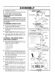
ASSEMBLY TOOLS REQUIRED FOR ASSEMBLY LEVER 1 - Knife (to cut carton and plastic ties/ LEVER 2 - 1/2 inch wrenches (or adjustable wrenches) CABLE 2 - 9/16 inch wrenches (or adjustable wrenches} 2- CABLE 3/4 inch wrenches (or adjustable wrenchesl MBLY 1 - Pliers (to spread cotter pin) 1- Screwdriver SHIFTER LEVER 1 - Measuring tape or ruLer DEFLECTOR Figure 1 shows the snow thrower in the shipping position Figure 2 shows the snow thrower completely assembled.
ASSEMBLY • Assemble the snow chute. • Roll snow thrower off the skid by pulling on the handle. • Properly dispose of discarded packaging. BRACKETS HOW TO SET UP YOUR SNOW THROWER SPRING _ CHUTE EXTENSION _ #L ...... NOW CHUTE DEFLECTOR Your snow thrower is equipped with height adjust skids (See FIG. 2) on the outside of the auger housing. To adjust the skid height, see To Adjust Skid Height paragraph in the Service & Adjustments section of this manual. (See Figure 1 page 20).
ASSEMBLY Bend the ends of the cotter pin around the rod and reinstall the plastic cap. PLASTIC \ Tighten the eye bolt installed earlier, keeping eye in line with the rod while tightening the inside securely CAP Rotate the chute crank fully clockwise and tullycou nterclockwise. The discharge chule should rotate fully to the outer diameter of the worm and should clear approximately 1/8" (See FIG. 5).
ASSEMBLY TO INSTALL THE SHIFTER LEVER Stand the snow thrower up on the front of the auger housing, as shown in FIG.8A. Note: Place a piece of cardboard under front to prevent paint damage to auger housing. SHIFTER BRACKET Cut the plastic tie which holds the shifter lever assembly to the shift bracket (FIG. 8B). Remove the Iocknut, (PIG. 8D). washer, spring and bolt A Reposition the shifter lever into the slot in the control panel, as shown in FIG.
OPERATION KNOW YOUR SNOW THROWER READ THIS OWNER'S MANUAL AND SAFETY RULES BEFORE OPERATING YOUR SNOW THROWER. Compare the illustrations with your snow thrower to familiarize yourself with the location of various controls and adjustments. Save this manual for future reference. -TRACTION DRIVE LEVER AUGER DRIVE LEVER HEADLll CRANK ASSEMBLY SPEED SHIFTER LEVER CHUTE DEFLECTOR LEVER CTRIC CHUTE DEFLECTOR TER CHUTE IGNITION KEY \ _' _.
OPERATION The operation of any snow thrower can result in foreign objects being thrown into the eyes, which ca. result in severe eye damage. Always wear safety glasses or eye shieJds while operating the _now thrower. We recommend standard safety glasses or wide vision safety mask for over your glasses available at SEARS Retail Stores or Service Centers. HOW TO USE YOUR SNOW THROWER TO STOP YOUR SNOW THROWER • To stop throwing snow, release the auger drive lever (See FIG. 4).
OPERATION TO USE WHEEL • LOCKOUT PIN The left hand wheel is secured to the axle with a klick pin (See FIG. 5A). This unitwas shipped withthis klick pin in the locked (through wheel hole) position. For ease of maneuverability in light snow conditions, disconnect the klick pin from the wheel locked position and push into the single wheel drive (unlocked axle hole only) position (See FIG. 5B).
OPERATION Do not prime if temperature is above 50°F. AND CAUTION MUST BE USED WHEN CAUTION: GASOLINE IS FLAMMABLE HANDLING OR STORING IT. Two times if temperature is 50°F to 15°F. Four times if temperature is below 15°F. DO NOT FILL FUEL TANK WHILE SNOW THROWER IS RUNNING, WHEN IT IS HOT, OR WHEN SNOW THROWER IS IN AN ENCLOSED AREA. Push down on the starter button until the engine starts. Do not crank for more than 10 seconds at a time.
OPERATION CAUTION: NEVER RUN ENGINE INDOORS OR IN ENCLOSED, POORLY VENTILATED AREAS. ENGINE EXHAUST CONTAINS CARBON MONOXIDE, AN ODORLESS AND DEADLY GAS. KEEP HANDS, FEET, HAIR AND LOOSE CLOTHING AWAY FROM ANY MOVING PARTS ON ENGINE AND SNOW THROWER. WARNING: TEMPERATURE OF MUFFLER AND NEARBY AREAS MAY EXCEED 150 '_F. AVOID THESE AREAS. DO NOTALLOW CHILDREN OR YOUNG TEENAGERS TO OPERATE OR BE NEAR SNOW THROWER WHILE IT IS OPERATING.
OPERATION SNOW THROWING CHOKE CONTROL TIPS For maximum snow thrower efficiency in removing snow, adjust ground speed, never the throttle. Go slower in deep, freezing, or wet snow. If the wheels, reduce forward speed. The engine is designed to deliver maximum performance at full throttle and should be run at this power setting at all times. IGNITION KEY THRO'rrLE RECOIL STARTER • Most efficient snow blowing is accomplished when the snow is removed immediately after it falls.
CUSTOMER RESPONSIBILITIES SERVICE RECORDS Fill In dates as you complete regular service SCHEDULE After First 2 hours Before [ Each As Use Needed Check Engine Oil Level ' Every 10 Hours Every 25 Hours p,4 Change Engine Oil _ Tighten All Screws and Nuts _ SERVICE DATES Each Season Before Storage pJ Jr_ /_ pJ pJ _, _' _ Check Traction Clutch Cable Adjustment (See Cable Adjustment) PJ Replace Spark Plug _justDAve Bolts ii' Lubricate All Pivot Points _ Lubricate AugerShaft(SeeShear p,
CUSTOMER RESPONSIBILITIES SNOW THROWER LUBRICATION - EVERY TEN HOURS Auger Shaft - Using a hand grease gun, lubricate the auger shaft zerk fittings (See A, FIG, 2) every ten (10) operating hours. Each time a shear bolt is replaced (See To Replace Auger Shear Bolt paragraph in the Service & Adjustments eectlon of this manual), the auger shaft MUST be greased. -__AXLE AXLE_ For storage or when replacing shear bolts, remove shear bolts and lubricate auger shaft zerks. Rotate augers several times on the .
CUSTOMER RESPONSIBILITIES LUBRICATION • I Hex Shaft and Gears - Hex shait and gears require no lubrication. All bearings and bushings =t? lifetime lubricated and require no maintenance (See FIG. 3). NOTE: OIL LEVEL MUST BE BETWEEN FULLAND ADD MARK NOTE: Any greasing or oiling of the above components can cause contamination of the friction wheel. If the disc drive plate or friction wheel come in contact with grease or oil, damage to the fdction wheel will result.
SERVICE AND ADJUSTMENTS I CAUTION: ALWAYS DISCONNECT THE I SPARK PLUG WIRE AND TIE BACK AWAY FROM THE PLUG BEFORE MAKING ANY ADJUSTMENTS OR REPAIRS. SKID MOUNTING NUTS TO ADJUST SKID HEIGHT O This snow thrower is equipped with two height adjustment skids, located on the outside of the auger housing (See FIG. 1). These skids elevate the frontof the snow thrower. For normal hard surfaces such as a paved driveway or walk, adjust the skids as follows: • Check tire pressure (14 to 17 pounds).
SERVICE AND ADJUSTMENTS TO ADJUST THE CLUTCH CONTROL CABLES CONTROL LEVER MUST BE IN FULL TRACTION DRIVE LEVER FORWARD POSITION (Just ContactPlastic Bumper) WHEN CHECKING "Z" FITTING Periodic adjustment of the cables may be required due to normal stretch and wear on the belts.
SERVICE AND ADJUSTMENTS TO REPLACE BELTS The drive belts on this snow thrower are of special construction and should be replaced with original equip merit belts available from your nearest Sears Store or Service Center. You will need the assistance of a second person while replacing the belts. Drain the gasoline from the fuel tank by removing the fuel line. Drain the gas and reinstall fuel line. I & DOORS, FROM OR FLAME. CAUTION:AWAY DRAIN THE FIRE GASOLINE OUT AUGER DRIVE BELT FIG.
SERVICE AND ADJUSTMENTS TRACTION DRIVE BELT TO ADJUST THE FRICTION It your snow thrower will not move forward, ':heck the tractiondrive belt for wear. It the traction drive belt needs to be replaced, proceed as follows: • Disconnect the spark plug wire. • Remove the belt cover (See FIG. 7 In this section). • Loosen belt guides (See FIG. B) and pull belt guides away from the engine drive pulley. • Loosen nut on auger idler and pull auger idler pulley away from belt.
SERVICE TO REPLACE AND ADJUSTMENTS FRICTION WHEEL I WHEEL ifthe snow thrower will not move forward, and the friction wheel is worn or damaged, you need to replace it. as follows: (First allow the engine to cool). BOLT LOCKWASHER HEX SHAFT _b CAUTION: DRAIN GASOLINE OUTDOORS AWAY FROM FIRE OR FLAMF / • Drain the gasoline from the fuel tank. • Disconnect the spark plug wire. I Stand the snow thrower up on the auger housing end (See FIG. 15). • Remove the bottom panel (See FIG. 13).
SERVICE AND ADJUSTMENTS TO REPLACE AUGER SHEAR BOLT The augers are secured to the auger shaft with special bolts (See FIG. 16) that are designed to break (to protect the mechlne) if an object becomes lodged in the auger housing. Use of a harder bolt will destroy the protection provided by the shear bolt. IMPORTANT: SHEAR °°'T TO INSURE SAFETY AND PERFORMANCE LEVELS, ONLY ORIGINAL EQUIPMENT SHEAR B O L T S SHOULD BE USED. WHEN REPLACING SHEAR BOLTS, BE SURE TO REPLACE SHEAR BOLT SPACERS.
SERVICE AND ADJUSTMENTS TO ADJUST OR REPLACE THE SPARK PLUG If you have difficultystarting your snow thrower, you may need to adjust or replace the spark plug. Follow the instructionsbelow. .030 GAP Replace the spark plug ifelectrodes are pittedor burned or if the porcelain is cracked. TO ADJUST: • Clean the spark plug by carefully scraping electrodes (do not sand blast or use a wire brush). • Be sure the spark plug is clean and free of foreign matedal. Check electrodes gap (See FIG.
- STORAGE THROWER INDOORS OR IN AN ENCAUTION: NEVER STORE YOUR SNOW CLOSED, POORLY VENTILATED AREA IF GASOLINE REMAINS IN THE TANK. FUMES MAY REACH AN OPEN FLAME, SPARK OR PILOT LIGHT FROM A FURNACE, WATER HEATER, CLOTHES DRYER, CIGARETTE, ETC. BOWL DRAIN To prevent engine damage (if snow thrower is not used for more than 30 days) follow the steps below, SNOW THROWER STORAGE • Thoroughlyclean the snow thrower.
TROUBLE SHOOTING POINTS TROUBLE Difficult starting CAUSE CORRECTION Defective spark plug Replace defective plug. Water or dirt in fuel system Use carburetor bowl drain to flush and refill with fresh fuel, Engine runs en'stlcelly Blocked fuel line or low on fuel Engine stalls Unit running on CHOKE Engine runs erratically; Water or dirt in fuel system Clean fuel line; check fuel supply; add fresh fuel (gasotine/oil Loss of power Excessive vibration mixture if 2 cycle engine).