OWNERS MANUAL MODEL NO. 625.349290 CAUTION Read All Safety Guides Before You Start to Install Your Dispensing System -- HOW TO INSTALL- HOW IT WORKS- CARE OF- -- SPECIFICATIONS -- -- REPAIR PARTS-SAVE THIS MANUAL Sears, Roebuck and Coo, Chicago, PRINTED IN U S A IL 60684 U.S.A.
TABLE OF CONTENTS PAGE NO, Safety Guides ........................................ What Does The Dispensing System Do ....... PAGE NO. 3 Electrical Wiring 3-4 Solutions to Feed and Feed Rate ............. ............................ 5 Controls Put The System Together ........................ 6 Keeping The System in Working Locating and Solution 7 Dimensions Tools and Materials Installing Needed ......................... Injecting ................ ....................................
I SAFETY GUnDES A Read all steps, guides and rules carefully before installing and using your new Solution A Check with your local public works department for plumbing, electric and sanitation codes. You must follow their guides as you install your dispensing system. Dispensing System. Follow all steps exactly to correctly install. Failure to follow them could cause personal injury or property damage. Reading this book will also help you to get all of the benefits from your dispensing system.
WHAT YOUR SOLUT OI water softener, installed on the outlet side of the and over 70 it's basic (alkaline) If the pH is less than 7 0, the water contains too much acid Acid pressure tank, filters and softens the water If you do not like a remaining chlorine taste, Sears has taste and odor filters to remove it, water corrodes galvanized and copper plumbing, and makes red or blue-green stains on plumbing fixtures, dishes and clothes It often addsa bitter (2) HYDROGEN SULFIDE WATER -- Many water supplie
TREATING WELL WATER PRE-TREATING PRIVATE WELL SYSTEMS ,&CAUTION: This much chlorine, at one time, could exhaust the activated carbon in a taste HAVING IRON BACTERIA -- Before you put the dispensing system together and install it, chlorinate the well if it contains million (ppm) of bacterial steps. and more than 10 parts per iron. Use the following odor 3 Open 1_ For each 50 gallons of water in the well, pour 1 quart of ordinary household bleach into it.
PUT YOUR DISPENSING - Take the holding nut off the suction valve and slide over the end of the tubing. Push the tubing onto the end tip of the valve as far as it will go, Slide the holding nut up and tighten with your finger& 1, Fasten the solution pump to the base with 4 nylon screws and nuts, as shown 2.
WHERE TO LOCATE YOUR Locate the system where... .... IT'S AWAY ......a 115 volt, 60 Hz electrical nearby. (See page 11) ...good pump source is A fresh air flow will cool the solution motor and carry away solution fumes. ..... the area is clean A power FROM DIRECT SUNLIGHT DAMAGE FROM SOLUTIONS, LEAKS THAT COU LD OCCUR, LIKELY DUE TO IS LEAST it's close to the solution injection point Read about the 3 ways to inject solution, below. and the air is free of dust. _ .
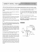
I BLENDING TANK Pressure Tank Tank Pressure BLENDING TANK 42 ga! minimum -- separate inlet & outlet -- no air bag or diaphragm BLENDING TANK 42 gal minimum -- separate inlet & outlet -- no air bag or diaphragm ' ,ill i Well I iI PRESSURE TANK INSTALLED "ON" THE MAIN SUPPLY LINE Pump Well I Well!_I I II CAPTIVE AIR PRESSURE TANK INSTALLED DISCHARGE SIDE OF WATER PUMP "ON" GUXDESTO nNSTALL YOUR (:_ SOLUTION INJECTION INTO THE WELL CASING NOTE: Looking at FIG.
GUBDESTO BNSTALL YOUR S (_) SOLUTION INJECTION INTO THE ALTERNATE DISCHARGE FITTING ON THE WELL PUMP 1. Turn off the electrical power to the well pump and turn off the gas or electric supply to the water heater 10. In the same way as in step 9, connect end of the tubing to the injection fitting 2. Open a faucet for a few seconds, water pressure, then close 11.
I GUIDES TO _) SOLUTION INJECTION BETWEEN THE WELL PUMP AND 1. Turn off the electrical power to the well pump and turn off the gas or electric supply to the water heater, 2. Open a faucet for a few seconds water pressure, then close to bleed 3o Close the shut-off valve on the main supply close to the pressure tank valve on the well pump, off to 1/4 in_ pipe thread. the threads 7. Put teflon for the length SEE PAGE 11 TO MAKE TRICAL CONNECTIONS. for leaks.
ELECTRICAL A WgRRNG GUIDE, € CAUTION: DO NOT TRY TO DO ANY WIRING IF YOU DO NOT KNOW ELECTRICITY. CALL A GOOD ELECTRICIAN A must follow 1. Looking at FIG.7and8or9, in a duplex, 3-prong, 115 " outlet Be sure to connect the the well pump pressure switch pump runs only when Receptacle local or national Conduit installand wire volt grounded outlet through so the solution the well pump -_ is on CAUTION: Many well pumps work on 230 volts.
I RLL THE TANK WnTH THE SOLUTION DISPENSING SYSTEM RESER- FEED CONTROL VOIR (TANK) HOLDS 15 GALLONS OF SOLUTION. HOWEVER, ON THE FIRST FILL, ALLOW SOME ROOM IN THE TANK SO THE SOLUTION STRENGTH CAN BE CHANGED IF NEEDED. DEPENDING ON THE WATER PROBLEM YOU ARE 3 KNOB ' TREATING, FILL THE TANK AND SET THE FEED RATE AS FOLLOWS. IRON AND -- Remove HYDROGEN the reservoir SULFIDE TREATMENT No. 1 settingis for the least solution feed. no 7is for the most, and no 4 is the mid-point.
I RLL THE TANK WroTHSOLUT 1. Residual still knob at 1 or 2-- above 0.6, and the feed control Use less chlorine in the mixture For example, use 1 gallon of bleach gallons of water instead of 1 to 1 for each 1. Opena nearby faucet to start the well pump and the solution pump 2. Follow the guides with the kit to test the water from the opened faucet 3. If the pH level is below7 0, turnthe feed control 2 2.
FILL THE TANK WnTH 3. Turn the relief-release valve (clockwise only FIG. 11, page 12) to the open position_ Solution is pumped through the suction tubing, into the pump head, then returned to the tank (takes 3-5 minutes). 4. When you see solution returning to the tank (look through fill hole), close the relief-release valve turning clockwise only_ The pump head is primed and will begin to pump solution out the discharge_ 5.
KEEP YOUR DaSPENSUNG RESERVOIR (TANK) SOLUTION LEVEL -- REMOVING After AND CLEANING THE PUMP HEAD installing the solution dispensing system, check the solution level in the tank daily. Red shows in CARTRIDGE VALVES -- Before the valves, open the relief-release removing any of valve. Be sure to the Low Level Indicator when about 5 gallons of solution remains. After awhile, you will know about how much solution it uses each day and how often to refill the tank.
I KEEPYOUR DUSPENSnNG LUBRICATION -- At least every 6 months, lubricate the solution pump as follows: SHAFT ASSEMBLY CAM 1. Unplug the electrical power cord, 2. Loosen the set screw in the feed control knob and remove the knob and bushing, 3. Remove the pump top cover, 4. Clean all the grease from the moving parts and inspect for wear, damage or corrosion. Replace parts as needed 5. Lubricate all parts with a premium grease, NOTE: If you replace any parts, adjust plate (FIG.
KEEP YOUR D SPENSING If the dispensing system is exposed to the sun, replace the solution tubing every6 months. Replace the tubing yearly if the system is installed indoors. CHECK THE INJECTION FITTING -- The plastic sleeve on the injection fitting helps to keep it clean and working_ However, check it every few months to keep it from plugging.
m 27 26 \ \ \ -N 25---'- MODEL NO. 625.
PARTS LiST KEY NO. PART NUMBER MODEL DESCRIPTION KEY NO. PART NUMBER NO. 625.349290 DESCRIPTION :;g m 1 818405 Float Assembly 19 9006056 2 818399 Pipe, Low Level Indicator 20 813533 Lock Washer 818510 Tank Cap 22 818408 Motor, 4 8800650 Tank, 23 818215 Motor Housing 5 U0812612 24 818285 Regulator 6 818382 Tank Base 25 8800656 Drive 7 811704 Nylon Nut (4 req.
S AI S OWNERS MANUAL SERVICE MODEL NO. 625.