SFo _u_h_ '_e"_r"unle _ SWA/_S owner's manual CATALOG NO. 9-29012 9-29013 FITS THE FOLLOWING MODEL NUMBERS: 113.197110, 113.197111 113.197150, 113.197151 113.197210, 113.197211 113.197250, 113_197251 113.197410, 113.197411 113.197510, 113.197511 113.197610, 113.197611 113.197180, 113.197181 SEA/A_S/ I:RRFT$ M gN_ 10-INCH RADIAL SAW GUARD KIT FOR YOUR SAFETY: • assembly • operating • repair parts READ ALL INSTRUCTIONS CAREFULLY Sold by SEARS, ROEBUCK Part No. SP5623 AND CO., Chicago, IL 60684 U.S.A.
Table of Contents Section Title ................................................................................ Page Safety ........................................................................................................................ 3 Assembly .................................................................................................................. 8 Repair Parts ............................................................................................................
Safety This manual has safety information and ins_ctions to help users eliminate or reduce the risk of accidents and injuries, including: 1. Severe cuts, and loss of fingers or other body parts due to contact with the blade. 2. Eye impact injuries, and blindness, from being hit by a thrown workpiece, workpiece chips or pieces of blade, 3. Bodily impact injuries, broken bones, and internal organ damage from being hit by a thrown workpiece 4.
Safety Kickback Hazard Kickback is the uncontrolled p_opelling of the workpiece back toward the user' during ripping° The cause of kickback is the binding or pinching of the blade in the workpiece° Several conditions can cause the blade to kWARNING KICKBACKII bind or pinch. When a workpiece kicks back, it could hit hard enough to cause internal organ injury, broken bones, or death. Wrong Way Feed Hazard Wrong way feed is ripping by feeding the workpiece into the outfeed side of the blade.
Safety Safety Instructions Read and follow all safety instructions, Personal Safety Instructions 1. Wear" safety goggles labeled "ANSI Z87.1" on the package, tt means the goggles meet impact standards set by the American National Standards Institute. Regular eyeglasses are not safety goggles. 2. Wear close fitting clothes, short sleeved shirts, and non-slip shoes. Tie up long hair. Do not wear gloves, ties, .jewelry, loose clothing, or long sleeves.
Safety Saw Safety Instructions 1_Use guard, pawls and riving knife according to instructions. Keep them in working order. 6. Before turning on saw, clear table of all objects except workpiece to be cut and necessary fixtures, clamps, or feather-boardso 2_Routinely check saw for broken or damaged parts. Repair or replace damaged parts before using saw. Check new or rep_ed parts fbr alignment, binding, and correct installation. 7. If blade jams, turn saw off immediately, remove yellow key, the free blade.
Safety 3. Rip only workpieces longer than the diameter of the blade. Do not rip workpieces that are shorter than the diameter of the blade being used. 4. Workpieces that extend beyond the saw table can shift, twist, rise up from the table, or fall as they ar'e cut or afterwards. Support workpiece with table extensions the same height as the saw table. 5. To prevent tipping, support outer ends of extensions with sturdy legs or an outrigger. 6.
Assembly Identify Parts 3he h_!lowing Nole: B@nv m_t assemble parts can toRethet: Parts) paris are inchided: beginning guar_L get Check assembl3; _mtact check your lost in packaging packaging that all parts Sear_ Service material. for' missing is at the end oJ the nlanual. IJst of hmse parts with catalog are included Center Do not throw palts away bcjbre contacting Use the list to identij], If you ate missing to get the missing part.
Assembly Guard Installation 1. Remove screws, existing Steps table boards. nuts and washers, Keep including Note: all tional clearance the lev- boards elling screws in the center of the front table. Discard the old table boards but keep the fence.
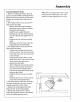
Assembly 7, Rotate the saw to the negative 45 degree l_'cx,_c! position. Remove and discmd ttle oflmr lmndle retaining screw, Discard tile old handle, 8. Using the two #1(1 x 3/4 flat head screws provided, altach the new h;mdle in tile same way as the old one was renloved, Top Motor Cover Screw Motor Cover Panel 9o Return lhe saw to the blade vertical, crosscut position.
Alignment Align Riving Knife to Blade The goa! of this adjustment is to position the riving knife directly in line with the blade. Riving knife alignment is an important safety factor, The riving knife rides in the kerf of the cut work_iece during ripping to keep the two sides of the workpiece from pinching on the blade. Blade pinching is a cause of kickback, Correct 1. Lock yoke in in-rip position (blade towards column, motor towards front of arm). 2. Lower arm until blade just clears table, 3.
Controls Miter Lock Yellow Ke Bevel Lock dwheel 12 Function Operation/Comments Miter Lock Frees radial arm to move; locks in any desired position; pro-set indexed positions at 0 °, 45°L, 45°R Pull out unlock, Hold in moving On-Off Switch Turns motor on!off Pull on, push off Requires yellow key Yellow Key Allows saw to be switched on Insert into on-off switch Remove after turning saw off Bevel Lock Frees motor to rotate; locks in any desired position; pre-set indexed positions at 0°, 45 °, 45
Controls Rip Scale & Rip Lock Rip lnd'_a,ors .__ _-._.,.
Controls Control Function Qoeration/Comm_nts Guard Clamp Screw Secures guard to motor; frees guard for removal Turn counterclockwise to loosen, clockwise to tighten Guard Protects against contact with upper blade; partially protects against contact with lower' blade; acts as sawdust deflector' Upper part remains fixed in level position.
Controls Pawls Riving Knile Knob Pawls \ Riving Knife Control Function Operation[Comments G u ard Tab Provides manual way to raise clear plastic guard during ripping when workq_iece fails to raise it Push and hold until workpiece clears guard, daen release Pawls!Riving Knife Knob Frees pawls and riving knife to independently move up and down Turn countmclockwise to loosen, clockwise to tighten Pawls During ripping, slow or stop kickback by digging into workpiece; when lowered during crosscuttin
Notes 16
PARTS LIST CRAFTSMAN 10" RADIAL SAW GUARD KIT CATALOG 9-29012 & 9-29013 Always order by Part Number - Not by Key Number FIGURE 1 Key No 1 Part No.
PARTS LIST CRAFTSMAN CATALOG Always 10" RADIAL SAW 9-29012 & 9-29013 order by Part Number GUARD KIT - Not by Key Number in 1 7 6 el=l= U) 8 9 34 33 33 / 31 10 35 11 17 3O 16 24 12 1 14 2O 28 27 FIGURE 2 13
PARTS LIST CRAFTSMAN 10" RADIAL SAW GUARD CATALOG 9-29012 & 9-29013 KIT Always order by Part Number - Not by Key Number FIGURE 2 - GUARD Key Pa_ No ...... No.
f ( I owner's manual 10-1NCH RADIAL SAW GUARD KIT SERVICE For the repair or replacement parts you need Call 7 am -7 pro, 7 days a week 1-800-366-PART (1-800-366-7278) CATALOG NO.