another free manual from www.searstractormanuals.com .1 ·r(' PIc', Sears 6 r f'/) 0 1 Oe.L 1f Cf/7 ~5 7 ~6 " 38/1 ROTARY MOWER MODEL NO. 91 Z 252031 FOR CUSTOM TRACTORS • • • • Assembly Operating Maintenance Repair Parts Sears, Roebuck and Co., Chicago, Ill. 60607 U.S.A. and Simpsons Sears Limited, Toronto 3828R-8.1.73 PRINTED IN u. S. A.
During the first year, we wi II repair your mower free of charge if found defective in material or workmanship. This guarantee service is avai lable by simply contacting any of our stores or service centers throughout the United States or Canada. The guarantee is limited to 30 days if the item is used for commercial purposes. IMPORTANT another free manual from www.searstractormanuals.com RULES FOR SAFE OPERATION 1. Know the controls, and how to stop quickly READ THE OWNER'S MANUAL. 2.
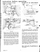
reference drawing for assembly and instructions MOWER CLUTCH CABLE CLUTCH LEVER another free manual from www.searstractormanuals.com {mower} REAR PIVOT LINK R.H. GEAR BOX R.H. DEFLECTOR SHIELD MOWER HOUSING FIG. 1 Thi s tractor or attachment has been designed, engineered and manufactured to give you the best possible dependabi I ity and performance. Should you experience any yroblem you cannot ~?S i Iy remedy, plea~e contact 'y?ur nearest Sears Roebuck or Sim.psonsSears, Ltd. Service Dept.
table of contents GUARANTEE ASSEMBLY INSTRUCTIONS 3-6 OPERATING 7-8 MAINTENANCE 8-9 REPAIR PARTS 10-14 another free manual from www.searstractormanuals.com FIG.3 4. Refer to Fig. 3. Assemble lifter bracket (E) to R.H. side of tractor frame (C) as shown. Secure I ifter bracket to tractor frame with 1-3/8 x 1 hex bolt, (head to outside) lockwasher, and hex nut provided. Leave bolt loose. 5. Refer to Fig. 2. line up rear hole of quadrant (F), L.H. tractor frame (C), and mounting channel.
asselT,lbly (cont.) Normally the wheels should be assembled to the bottom hole. Thi 5 wi II give a normal cutting height of approximately 1·7/8 inches. See Fig's. 21 and 22, Page 7. assembly of deflector shield to mower housing assembly of mower for tractor without clutch another free manual from www.searstractormanuals.com lever (mower) A FIG. 5 1. Refer to Fig. 5.· Remove bolt (A) from rear of mower housing (discharge end). 2.
3. Refer to Fig. 11. PI ace belt (G) on pulley (H) of cross shaft, and on idler pulley (J) as shown. Assemble largest spring (K) from idler bracket (C) to mounting angle rear (l) as shown. IMPOR· T ANT: long hook of spring (K) must be to idler bracket (C) and hook end away from belt (G) as shown. 4. Refer to Fig. 10. Rotate blade clutch handle (E) forward.
9. Refer to Fig. 16. Swing cable (U~ arol~nkd (so) that it will be between R.H. front pivot In N and R.H. front tractor tire. assembly (cont.) \~ \ I another free manual from www.searstractormanuals.com ~~\ 10. Refer to Fig. 17. Insert rivet pin in cable clevIs (A), and secure with cotter pin provided. 11. Refer to Fig. 16 & 17. Slip cable clevis (A) with pin on clutch lever (mower) (V) on tractor, as shown. Attach clutch cable anchor (W) to gusset Fig. 16 on R.H.
instruction before operating height of cut adiustment adiust mower from side to side GAUGE WHEEL. CUTTING :A~~ \ /' ......... " / I \ ( another free manual from www.searstractormanuals.com \ - --- - r APPROX. HEIGHT OF CUT \ \ " ""--........ - --- FIG. 19 ../ / FIG. 21 APPROX, HEIGHT OF CUT ADJUSTMENT L.IFTER ARM FIG. 22 ,- -- The cutting height of this mower is determined by the position of the gauge wheels on the cutter head or by the po sition of the I ifter arm.
OPERATING INSTRUCTIONS 4. Make left hand turn s when mowing, this spreads the grass clippings evenly over the grass which has been cut. Grass is mowed regularly (do not let grass get too high), there is little or no raking necessary after mowing. BEFORE CUTTING AN UNFAMILIAR PLOT OF GRASS, ALWAYS STOP TO ANALYZE THE LAWN OR FIELD FOR BEST MOWING PROCEDURE. CONSIDER ALSO THE HEIGHT OF GRASS TO BE MOWED. TYPE OF TERRAIN (LEVEL, HILLY OR PITTED), AS WELL AS THE PRESENCE OF ROCK OR TRASH.
maintenance {cont.} Threads on shaft are R.H. Remove spring washer, and slip blade from blade safety drive washer. Remove bl ade safety washer and sh i eld from sh aft and examine. I F DAMAGED, REPLACE. TWO EXTRA BLADE SAFETY DRIVE WASHERS WERE SHIPPED WITH MOWER. Reassemble shield, blade safety drive washer, blade, spring washer, and nut. Tighten nut securely. NOTE: REFER TO FIGURE 24 FOR SEQUENCE OF REPLACING BLADE. blade care i For best results, cutting blade must be kept sharp.
to remove mower fro m tractor (cont.) ~ belt replacement The mower drive belt can be replaced without removing mower head from mower if so desired. See steps below for removing belt. \ another free manual from www.searstractormanuals.com 1. Remove mower from tractor. See "To Remove Mower From Tractor", pages 9 & 10. FIG. 27 4. Refer to Fig. 27. Remove retainer spring,s (D) from pivot shaft (E) and slip rear pivot links (K) from ends of shaft. Replace retainer spring on shaft to prevent losing them.
• repair parts another free manual from www.searstractormanuals.com 38" ROTARY MOWER--MODEL NUMBER 917.252031 -24 , 25-+ I 5 Q' , , ®,~81 E(e==~e~ __ 82 I A. G .B5--§~_B3 , ~-84 1---28 ~--27 ABC 0 E F G H iii Iii • , ®87 @88 ~28 ~ 88 ~28 ®90 @88 ®90 ®87 ® 89 ®84 @89 ®84 ~88 ® 89 @88 @86 ®89 @89 3828R·8.1.
• repair parts i_ 38" ROTARY MOWER--MODEL NUMBER 917.252031 KEY NO. another free manual from www.searstractormanuals.com )J (e PART NO. 1 2 3 4 5 6 _. 7 794042 786028 788039 2037R 5231H 776085 792027 8 9 10 11 12 13 14 786059 794041 511P 626A271 7717H2 626A355 974R 15 16 17 18 19 20 21 22 23 24 25 26 27 28 29 30 31 32 33 34 35 36 ...].a..
The Model Number will be found on a plate attached to the'L.H. side of the housing mount assembly. Always mention the Model Number when requesting service or repair parts for x.,our 38" Rotary Mower. another free manual from www.searstractormanuals.com ISears I owners manual All parts listed herein may be ordered through SE;ARS, ROEBUCK AND CO. or SIMPSONS-SEARS LIMITED.