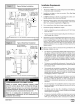
N9MP1 & N9MP2 *9MPD *Denotes Brands 90 Single Stage (C, H, T) FAN ASSISTED, DIRECT Category IVFurnace VENT GAS FURNACE REQUIREMENTS SAFETY Recognize safety the potential for personal Understand most serious death. hazards, those used service performed by trained to or shipped Follow all safety t_ identify the unit codes.
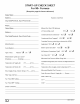
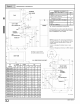
START-UP CHECK SHEET For 90+ Furnace (Keep this page for future reference) Dealer Name: Address: Business Card Here City, State(Province), Zip or Postal Code: Phone: Owner Name: Manual Gas Shut-Off Upstream YES of Furnace/Drip- Leg? Address: City, State(Province), NO YES Condensate Drain Connected? NOE_ Zip or Postal Code: Condensate Drain Trapped? NO YES Transition Pressure switch hose relocated for U/D/H Model Number: Application? YES _ Serial Number: Blower Speed Checked? NO YES
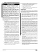
1. Safe Installation Requirements FIRE, EXPLOSION, AND ASPHIXlATION HAZARD Improper adjustment, alteration, service, maintanence or installation could cause serious injury, death and/or property damage. Installation or repairs made by unqualified persons could result in hazards to you and others. Installation MUST conform with local codes or, in the absence of local codes, with codes of all governmental authorities having,jurisdiction.
Have someone check the structure frequently during cold weather to make sure it is warm enough to prevent pipes from freezing. Instruct them on a service agency to call to provide service, if required. FrozenWater Pipe Hazard WATER DAMAGE TO PROPERTY HAZARD -or- Failure to protect against the risk of freezing could result in property damage and/or personal injury.
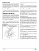
Installation Requirements Typical Upflow Installation 1. Aluminum or non-rusting shield recommended.(See Vent TerminationShieldingfor dimensions). *8" 20' Min. Max. _l[q in same _ _I_ _ Inlet Pipe (not used on Single atmospheric zone __4t_ Pipe model) <_ VentPipes MUSTbe Coupling on ends of exhaust pipe. Total Install This furnace is NOT to be used for temporary heat of buildings or structures under construction. 3. Install the vent pipes Installation section). 4.
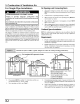
Dimensions & Clearances MINIMUM CLEARANCES TO COMBUSTIBLE MATERIALS FOR ALL UNITS r-- ] TOP | REAR O FRONT (combustion air openings in furnace and in structure) 3" Required For Service _A_ B_ ] LEFT SIDE I [-_ _ 11/4 TRAP(COUNTERFLOW) _ GASt_ FRONT 1" SIDES O VENT O TOP OF FURNACE 1" *30" clearancerecommendedfor casing removal.
Installation Positions drain line must be provided. for further details. This furnace can be installed in an upflow, horizontal (either left or right) or downflow airflow position. DO NOT install this furnace on its back. For the upflow position, the return air ductwork can be at- Leveling tached to either the left or right side panel and/or the bottom. For horizontal and downflow positions, the return air ductwork must be attached to the bottom.
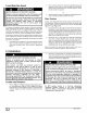
3. Combustion For Single & Ventilation Air Air Openings and Connecting Ducts Pipe Installation Total input rating for all non direct vent gas appliances MUST be considered when determining free area of openings. CARBON MONOXIDE POISONING HAZARD Failure to provide ventilation air could injury. adequate combustion and result in death and/or personal Use methods described and ventilation air. here to provide 2, Connect 3. When screens are used to cover no less than 1/4" mesh. 5.
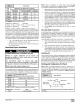
NOTE: Refer to definitions in section Construction, If any one of the conditions be considered confined space regardless Free Area BTUH MinimumFreeArea Requiredfor Each Opening Input Rating HorizontalDuct (2,000 BTUH) Vertical Ductor openings to outside(4,000 BTUH) Round Duct (4,000 BTUH) 50,000 25 sq. in. 12.5 sq. in. 4" 75,000 37.5 sq. in. 1825 sq. in. 5" 100,000 50 sq. in. 25 sq. in. 6" 125,000 62.5 sq. in. 3125 sq. in. 7" 150,000 75 sq. in. 37.5 sq. in.
For Two Pipe Installation CARBON MONOXIDE POISONING HAZARD Failure to follow the steps outlined below for each appliance connected to the venting system being placed into operation, could result in carbon monoxide poisoning or death: The following steps shall be followed for each appliance connected to the venting system being placed into operation, while all other appliances connected to the venting system are not in operation: 1.
bustion orthefurnace canuseairfrominside thestructure forcombustion. TheINLETairpipeisoptional. Ifcombustion aircomes frominside thestructure, adequate makeupairMUST beprovided tocompensate foroxygen burned. SeeConfined Space Installation in the Combustion and Ventilation Air chapter. If combustion air is drawn from outside the structure, it MUST be taken from the same atmospheric pressure zone as the vent 4.
3. Insulate combustion air inlet piping mid spaces such as basements. Sizing Combustion Consult when run in warm, hu- Air and Vent Pipe Table 3 or Table 4 to select the proper diameter exhaust and combustion air piping. Exhaust and combustion air piping is sized for each furnace Btuh size based on total lineal vent length (on inlet oroutlet side), and number of 90 ° elbows required. Two 45 ° elbows can be substituted for one 90 ° elbow.
Item A Clearance Canadian Installation (1) Description U.S.
Item A Canadian Installation (1) Clearance Descriptions U.S.
CondensateDrain Trap This furnace removes both sensible and latent heat from the products of combustion. Removal of the latent heat results in condensation of the water vapor. The condensate is removed from the furnace through the drains in the plastic transition and the vent fitting. The drains connect to the externally mounted drain trap on the left or right side of the furnace.
Upflow Installations Top Vent ONLY Caps(2) ellowor black Plastic _ Co_ (Optional) VentDrain & Clamps Pressure Switch Detail le Pressure Switch ID RubberTube 1/2" ID Drain StreetEIbow /'CPVC (Looseparts bag) Drain Connector Black PVC 3/4"PVC X l/z" CPVC (Loose parts bag) Casing Grommet Black Rubber 5/8" ID (Loose parts bag) Drain Line Vent Tee 3/4"PVC or l/z" CPVC(Field supplied) Drain Tube(& Clamps) Black Rubber /8 ID, Cut length to fit (Loose parts bag) Upflow Remove will exit.
UpflowInstallationsVentthru LeftSide Yellow or black Plastic Cap 2" PVCCoupling ONLY Coupling oj Either: The PVC Drain Tee or a field supplied 2" PVC Te_ Vent Drain & Clamps Dual Pressure Switch Detail Single Pressure Switch ID RubberTube Tee Trap White PVC (loose parts bag) Sl8" ID Hose & Clamps Black (Move from bottom of drain tee if installed) DrainConnector Black PVC 314"PVCX 112"CPVC (Looseparts bag) SIDE VIEW ,,,_ Rotate downward Casing Grommet Black Rubber s/8" ID (Loose parts bag)
All ModelsVentthru RightSide 4} Yellow or black Plastic Cap On Some Models ONLY 2" PVC Coupling Either: The PVC Drain Tee or a field oJ Vent Drain & Clamps supplied2" PVC Tee Single Dual Pressure Pressure Switch Detain Switch Tee Trap White PVC & Clamps ElbowsTubes (2) & Clamps Black, 1/z" ID (loose parts bag) Barbed Coupling, 112"OD parts bag) Drain Line Vent Tee 3/4" PVC CPVC(Field supplied) SIDE VIEW _otate downward 314"PVCX 1/2" CPVC (Loose parts bag) Casing Grommet "Black Rubber sis" CPV
DownflowLeft Side Vent and Trap SIDE VIEW Yellow or black Plastic Cap /,,_ Coupling&Clamps >_ (Optional)_ I._ Rotate downward 2" PVCCoupling NOTE_. Bw]t-in channel will be angled 5° to 10° also. VentDrain & Clamps ]|mm|l Either: The PrO Drain Tee or a field supplied 2" PVC Tee Dual Pressure Switch 3/16"ID Tee Trap Whtte PVC___ On Some Models ONLY _ INLET _) 4= (looseparts bag) -__ Single Pressure Switch Hose Detail Connector, 3/16" OD (loose parts hag) E,how!l _1 WARNING _.
Downflow Yellow or black Plastic Right Side Vent and Trap Cap Trap Connection _Clamp ears '_ ointed OUT / Vent Drain Pmassemble& insert intofurnace & Clamps 3/16" ID Rubber Tube SIDE VIEW ,_Rotate downward Coupling & Clamps Splice Connector Barbed 112"ID Drain Hose & Clamps Dual Pressure Switch On Some NOTE.'_Built-in channel will be angled 5° to 10° also.
Horizontal Vent Drain & Clamps Left Thru Top Single Yellowor black Plastic Pressure Switch Detail Trap Connection _ %lamp ears" Pointed OUT Preassemble & Alternate insert into furnace Orienation 3116" Dual Pressure Switch _Rubber ID Tube ] _ _ _I ' i Relief Tube Extension ReliefTube _io16"neODtoFr lexibletubing 1/2" ID Drain Hose & Field Supplied Tee (Optional) Clamps TubeBlack, /8 ID Corrugated Cut at straight section Tee Trap White PVC (loose parts bag) Cap and Clamp Open End L
Horizontal Left-Side Vent Single Pressure Alternate Switch Detail Orienation Yellow or black Field Supplied Tee_ Level or Sloped towards Dual Pressure Tee VentDrain & Clamps Switch 3/16"ID Ru/bherTube 1/2" ID Drain Elbow _Drain Hose & Splice Connector (Cut-to- fit) Tee Trap White PVC (loose parts bag) ,5/8" ID Corrugated Relief Tube / / U DrainTube Black, /8 ID Corrugated Cut at straight section I Leav_ Splice Connector Relief Tube Extension WARNING MoveCaps to top of trap Cut Here 25-24-4
Horizontal Right thru Top Single Pressure Trap Connection Switch Detail "Clampears" Alternate Yellowor black Orienation _> _ _i_> Preassemble & insert into furnace Coupling & Clamps I-& Clamps VentDrain (Optional)_ WARNING "_ Add Cap and _ 3/16"ID RubberTube\\ Field S/uppliedTee _,_X Clamp Splice Connecto Relief Tube Extension_ _.
HorizontalRight-SideVent Single Pressure Switch Detail Yellowor black Coupling & Clamps ptional) VentDrain & Clamps Fiel_lied Tee Level or Sloped towards Tee N _= /2" ID Dr =in (looseparts bag) Elbow On Some Models /ONLY SpliceConnector / ReliefTube Extensionj_/ Alternate o i Dual Pressure Switc_ DrainTube Black, s/8" ID // Ct°[riugatedCut at Leaveroomfor/ clamP Horizontal Disconnect Right Side ('9MPD models only) cover plate and gasket provided hole from the burner compartment se
iiiiiiiiiiiiiiiiiiiiiiiiiiii! ¸I¸! !!ii¸!iii¸I¸I ¸I¸I¸!!i!i!!!i ¸jijiii ii!!iil i!ii!i Connecting Tee Trap to Condensate Trap and Main Drain Line Open Tee \ Tee Trap/_---_ E B Condensate Trap Evaporator Coil ,m o Drain Line (Optional)-.................._]_E Main Drain Line o_ / & 25-24-41N The Tee Trap must be connected to the main condensate drain Connecting Vent and Combustion Air Piping line as conceptually shown above.
The air intake coupling is sized for 2" PVC pipe. Install the combustion air pipe to the air intake coupling sealant to provide for future serviceability. using RTV Vent Pipe Connection Install the vent • pipe grommet to the furnace panel. Locate grommet in the furnace panel at a location directly away from vent fitting on the combustion blower. The grommet snaps into 3" hole plug from the furnace panel.
1, Install all couplings, nipples and elbows using proper procedures for Joining Pipe and Fittings and maintain spacing between vent and combustion air piping as indicated in Figure 20 through Figure 28. ......................................................................... _!i i I °rGradesidewallLeveITerminati°n Risers t° Get Ab°ve sn°w with 8" Exterior Level * MIN. _ "18" Minimum for cold climates 20' JW MAX (substained below 0° F) 8" MIN.
Multi Vent Termination Clearances When two (2) or more furnaces furnace must be individually are vented Sidewall Inlet Vent and Exhaust-Air Termination with Exterior Risers near each other, each 18" Min. for Cold Climates_ (SustainedBelow 0° F) vented. 8" Min. Two (2) vent terminations may be installed as shown in Figure 23, Figure 24, Figure 25, Figure 26, Figure 27 and Figure 28, but the next vent termination must be at least 36" away from first 2 terminations.
5. Gas Supply and Piping CARBON MONOXIDE EXPLOSION HAZARD. POISONING, FIRE AND 2. Gas input to burners MUST NOT exceed the rated input shown on rating plate. 3. Do NOT allow minimum gas supply pressure to vary downward. Doing so will decrease input to furnace. Refer to Table 6 for normal gas supply and manifold pressures. Failure to follow these instructions could result in death, personal injury and/or property damage.
MANIFOLDPRESSUREAND ORIFICE SIZE FOR HIGHALTITUDEAPPLICATIONS iiiiiiiii_ ii_!!!!!!! i NATURAL GAS MANIFOLD PRESSURE (" w.c.) .............................................................. FOR THE 50,000, 75,000, 100,000 and 125,000 BTUH MODELS MEAN ELEVATION HEATING VALUE at ALTITUDE BTU/CU. FT, 0 to 2000 Orifice No. 2001 to 3000 Manifold Pressure Orifice No. 3001 to 4000 Manifold Pressure Orifice No. FEET ABOVE SEA LEVEL 4001 to 5000 Manifold Pressure Orifice No.
i iiiiiiiiiiiiiiiiiiiiiiiiiiiiiiiiiiiiiiiiiiiiiiiiiiiiiiiiiiiiiiiiiiiiiii_i_;!!_;_;:_;_;_!!!i!i!i!i!i!i!i!i_i_ ¸_;_!_i!_!i_iiiiiiiiiiiiiiii_iiiiiiiiiiii_iiiiiiiiiiiiiiiiiiiiiiiiiiiiiiiiiiiiiiiiiiiiiiiiiiiiiiiiiiiiiiiiiiiiiiiiiiiiiiiiiiiiiiiii_i; LPG or PROPANE GAS MANIFOLD i iiiiiiiiiiiiiiiiiiiiiiiiiiiiiiiiiiiiiiiiiiiiiiiiiiiiiiiiiiiiiiiiiiiiiiiii ili ii i! i ii FOR THE 80,000 HEATING VALUE at ALTITUDE BTU/CU, FT. 0 to 2000 10.0 #55 2500 Orifice Size BTUH PRESSURE (" w.c.
3. Timehowmany seconds ittakesthesmallest dialonthegas NOTE: Ifmeter usesa2cubic footdial,divide results (seconds) by metertomakeonecomplete revolution. Refer toExample. two. 4. Relight allappliances andensure allpilotsareoperating. !i!i!i!!ii !i!i ilii!iiii!! Typica, Gas Pipiog ,orU .ow Drip Legand Union,Union* shouldbe outside the dripleg, union, andfurnace. Gas Pipe Grommet(SinglePipe) Manual shut-off cabinet.
NOTE:RefertoFigure30orFigure31forthegeneral layoutat thefurnace. TheruleslistedapplytonaturalandLPgaspipe installations. NOTE: OntheDualCertified orDirect Ventmodels, installthegas pipegrommet tothefurnace sidepanel withthegaspipeentry. If needed, remove the2"holeplugandrelocate totheopenholein thefurnace sidepanel. Use two pipe wrenches when vent gas valve from turning. 7. Install pipe and fittings NOTE: The use of copper tubing by the state of Massachusetts. 5.
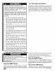
Control Center Fuse REDUCED FURNACELIFE HAZARD Failure to follow caution instructions reduced furnace life. Do NOT exceed 115V/0.8 load for both the EAC terminal combined. may result in The 24V circuit contains a 5-amp, automotive-type fuse located on fan timer board. (See Figure 33) Any electrical shorts of 24V wiring during installation, service, or maintenance may cause fuse to blow. If fuse replacement is required, use only a fuse of identical size (5 amp.) amp.
7. Ductwork and Filter Side Return Air Cutout CARBON MONOXIDE POISONING HAZARD. Failure to properly seal duct could result in death and/or personal injury. = Height of Cutout for 16" x 25" Filter AB 22112"141/2" Width of Cutout for 16" x 25" Filter _ rll Do NOT draw return air from inside a closet or utility room where furnace is located. Return air duct MUST be sealed to furnace casing.
Mounted Filter CAUTION Rack If filters are only suitable homeowner that filter size conditioning is added. for heating application, advise may need to be increased if air Addition Of Air Conditioning 25-20-90 Filter Installation using Optional Filter Rack When installing or removing a bottom mounted filter, slide the two side filter clips to the back of the furnace BEFORE installing or removing. This will allow the filter to clear the front raised edge of the furnace.
Subbases forCombustible FloorsDimensions Subbase forCombustible FloorDimensions H* J* K** Subbase for Combustible Floors Part Number Furnace Opening Opening In Base For Plenum In Floor Typical Plenum Dimensions M N P R S T Subbase NAHH001SB 1511/16 283/4 149/16 16 161/4 145/8 15 13112 15 131/2 NAHH002SB 195/16 283/4 183/16 16 161/4 181/4 15 17118 15 171/8 NAHH003SB 22_/16 28J/4 2113/16 16 161/4 21//8 15 193/4 15 19_/4 NAHH010SB 243/4 283/4 239/16 161/4 161/
Condensate Line Raised by Base 25-20-52 8. Checks and Adjustments Adjust Pilot Burner FIRE OR EXPLOSION HAZARD. The furnace has 3a pilot 1flame to light the main burner. The flame should surround /8' to /2' of the flame sensor. See Figure 42. To adjust, remove cap from pilot adjusting screw on gas valve. Turn screw counterclockwise to increase or clockwise to decrease Failure to turn OFF gas at shut off before connecting manometer could result in death, personal injury and/or property damage.
If it is necessary to change speeds, refer to steps below. Main Burner Refer to Furnace WMng Diagramfor location of the heating and cooling speed taps located on the electronic fan control as well as location of unused blower motor speed leads. Use the chart (Table 12) to determine the blower motor Face speed settings.
9. Furnace Maintenance FIRE, EXPLOSION, HAZARDS OR CARBON MONOXIDE ELECTRICAL HAZARD SHOCK, FIRE OR EXPLOSION Failure to have the furnace inspected and maintained could result in fire, explosion, or carbon monoxide poisoning. Failure to follow safety warnings exactly could result in dangerous operation, serious injury, death or property damage. It is recommended that the furnace be inspected and serviced on an annual basis (before the heating season) by a qualified service technician.
10. Sequence of Operation The following is the normal operating & Diagnostics sequence for the control system. Cooling (¥) Request: 24 VAC signals • Cool motor applied speed Y & G signals removed • speed Cool motor Circulating Cool fan timer) Fan On Delay control. time. EFT. de-energized applied after 90 second to G terminals Heat motor speed energized G signal • from of EFT (electronic after 5 second Cool Fan Off Delay time.
Gas Valve Diagnostic Codes (See Figure 44) OFF = Control Heartbeat 1 Flash = Normal Operation = Not used 2 Flashes = Pressure switch closed 3 Flashes = Pressure switch circuit in 5 minute delay mode, with inducer (Note: 4 Flashes not powered off.
HONEYWELL SV9541M "SMART I POWERAPPLIEDTO APPUANCE I THERMOSTAT VALVE" Sequence of Operation l I CALLS FOR HEAT ¢ WAITFOR PRESSURESWITCHESTO OPEN I PRESSURESWITCHESPROVED OPEN? i I COMBUSTIONBLOWER ENERGIZED I PRESSURESWITCHESCLOSEDWITHIN 30 SECONDS? _1_ COMBUSTIONBLOWERDE- ENERGIZED _[ J FIVE MINUTEWAIT PERIOD 3 SECONDPRE-PURGE I PILOT VALVE OPENS: IGNITORPOWERED(1) L FAILURE THREE SECOND RECYCLE FLAME DELAY PILOT LIGHTSAND FLAMEIS SENSED DURING90 SECONDTRAILFOR IGNITION? _I I_uI
HONEYWELL The 6 + X designation the reason LED the control SV9541M indicates went "SMART VALVE" a combi nation of flash codes: into soft lockout. Last status 6 flashes Trouble shows code indicates INDICATES the control repair shooting is in soft lockout, to address followed by X flashes to indicate first CHECK/REPAIR STATUS Line voltage input at L1 and Neutral connectors on ST9160B Fan Timer. Off No power to system control.
HONEYWELL LED STATUS SV9541M "SMART VALVE" INDICATES Trouble shooting continued CHECK/REPAIR SoftLockout. Last failure was pressure switch Ignition system control switch must be in the ON position. 6 Flashes + Maximum recycle count exceeded Pressure switches operation, tubing, and wiring. 3 Flashes Restrictions in furnace air intake or vent piping. Combustion air blower is de-energized, Circulating blower is de- High winds blowing against vent. energized after the "OFF" delay.
ticaltermination ispreferred• Fieldsupplied pipeandfittingsare required tocomplete theinstallation• Concentric Drawing Vent Dimensional Kit Components KitContents: 3" Rain Cap or 2" Rain Cap 311DiameterSDR-26 Pipe, 191121 '' Long or 4 DiameterSDR-26 Pipe, 371/8,Long, 2 DiameterSDR-26 Pipe, 315/8 Long or 21/2"DiameterSDR-26 Pipe,24" Long, 3" Y Concentric Fittingor 2" Y Concentric Fitting 13/16" Nominal3" or 4" Dia. 11/2" SDR- 26Pipe A • ¥ Concentric Fitting 2 or 21t2" Dia.
Concentric Termination Kit NAHA001CV & NAHA002CV Venting ........................................................ Table 50,000 NAHA002CV NAHA001CV for N9MP2 CARBON MONOXIDE POISONING HAZARD Models Failure to follow this warning could result in death, personal injury and/or property damage.
Concentric Attachment Vent Sidewall Strap 8. Install the rain cap and the small diameter pipe assembly in the Y concentric fitting and the large pipe assembly. Ensure that the small diameter pipe is bottomed out and securely cemented in the Y concentric fitting. 9. Cement the furnace combustion air and vent pipes concentric vent termination assembly. See Figure Figure 50 for proper pipe attachment. 10.
Four Position Furnace Models Single Pipe N9MP1050B12B1 N9MP1075B12B1 N9MP1080F16B1 N9MP1100F14B1 N9MP1100J20B1 N9MP1125J20B1 or Two Pipe N9MP2050B12B1 N9MP2075B12B1 N9MP2080F16B1 N9MP2100F14B1 N9MP2100J20B1 N9MP2125J20B1 or Dual Certified *9MPD050F12B1 *9MPD075F12B1 *9MPD080J16B1 *9M PD100J14B1 *9MPD100J20B1 *9MPD125L20B1 25-23-30 *Denotes International Comfort Lewisburg, TN 37091 Fast Parts Division 866-380-3278 Products, LLC Save This 440 01 102004 Brand Manual For Future Reference [_
Model Specifications Manufacturers Number (Mfr No -See Rating Plate) ALL Models Specifications (N9MP1) N9MP1050B12B N9MP1075B12B N9MP1080F16B N9MP1100F14B General GasType Input(Btuh) Output(Btuh) Transformer Size (VA) T'stat HeatAnticipator Temp. Rise (F) Nat./LP 50,000 45,500 40 .10 35-65 11516019.8 Electrical(VoltslHz/FLA) Gas & Ignition GasType GasValve Nat. L.P. Nat./LP 75,000 68,000 40 .10 40-70 11516018.9 Nat. L.
Manufacturers Number (Mfr No -See Rating Plate) ALL Models Specifications (N9MP2) N9MP2050B12B N9MP2075B12B N9MP2080F16B NPMP2100F14B N9MP2100J20B General GasType Input(Btuh) Output(Btuh) Transformer Size (VA) T'stat HeatAnticipator Temp. Rise (F) Nat./LP 50,000 45,500 40 .10 35-65 11516019.8 Electrical(Volts/Hz/FLA) Nat./LP 75,000 68,000 40 .10 40-70 11516018.9 Nat./LP 80,000 72,000 40 .10 35-65 11516019.0 Nat./LP 100,000 91,000 40 .10 40-70 N9MP2125J20B Nat./LP 100,000 96,500 40 .
Manufacturers Number (Mfr No -See Rating Plate) ALL Models Specifications ('_9MPD) *gMPD05OF12B *gMPDO75F12B *9MPD080J16B General GasType Input(Btuh) Output(Btuh) Transformer Size (VA) T'stat HeatAnticipator Temp. Rise (F) Nat./LP 50,000 46,000 40 .10 35-65 115/60/9.8 Electrical(Volts/Hz/FLA) Nat./LP 75,000 69,000 40 .10 40-70 11516018.9 *9MPD10OJ20B *9MPD125L20B Nat./LP 80,000 73,600 40 .10 35-65 Nat./LP 100,000 92,000 40 .10 40-70 Nat./LP 100,000 92,000 40 .10 40-70 Nat.
CIRCULATION AIR BLOWER DATA For 050 Models 3 Ton Units For 080 Models 4 Ton 19" & 22314" Units Speed Tap Low Med L Med H Hi 0.1 826 1083 1301 1408 0.2 804 1050 1242 1347 0.3 770 1028 1195 1295 = 0.4 735 985 1153 1237 0.5 698 952 1093 1183 0.6 657 909 1040 1118 0.7 --- 863 935 1053 0.8 .... 812 865 976 0.9 ...... 802 887 1.0 ...... 720 787 _d m $ X For 075 Models 3 Ton Units Speed Tap Low Med L Med H Hi 0.1 823 1109 1527 1850 0.
0 #., CONNECTION WARNING: ELECTRICAL SHOCK HAZARD DISCONNECT BEFORE SERVICING DIAGRAM R MAi-NUM_-TQ R FIELD CONNECTION BOX 60HZ SK _ NEUT_RAL_ t''''_ *GR /_ " I | INTERLOCK SWITCH _ 115V I IbOI I _1 I L_ [- _ VOLT I W 1612t _ --BE t IGNITER " I - ----- BL I II191 I L_ p !, :: / /_/.L//NOTE 2 L_ q ' I I I I I I............ , BL I I_ s'KI i _,l Id|l 11,)_2c COM b_Z/I jl _,l_llll q _ tLP_ ....
EE B AA YY 15 16 Y GG 18 X FF 12 \ UU CC VV <::::b \ LL H SS_ M KK MM HH MM \ 20 \ PP OO_ 25-23-95
I Replacement Parts - NgMP1 & NgMP2 Models N9MP105OB12B1, N9MP1075B12B1, N9MP108OF16B1, N9MP11OOF14B1, N9MP11OOJ2OB1 & N9MP1125J2OB1 - N9MP205OB12B1, N9MP2075B12B1, N9MP208OF16B1, N9MP21OOF14B1, N9MP21OOJ2OB1 & N9MP2125J2OB1 (Natural Gas) Replacement part supplied will be current active part. For parts not listed, consult place of purchase.
I Replacement Parts - NPMP1 & NPMP2 Models N9MP1050B12B1, N9MP1075B12B1, N9MP1080F16B1, N9MP1100F14B1, N9MP1100J20B1 N9MP1125J20B1 - N9MP2050B12B1, N9MP2075B12B1, N9MP2080F16B1, N9MP2100F14B1, N9MP2100J20B1 N9MP2125J20B1 (Natural Gas) Replacement Key No. A B F part supplied Description Non-Functional Panel,Top Gasket,Top Panel Partition,Blower H Housing,Blower J Panel,BlowerCutoff will be current active part.
I Replacement Parts - NPMP1 & NPMP2 Models N9MP105OB12B1, N9MP1075B12B1, N9MP108OF16B1, N9MP11OOF14B1, N9MP11OOJ2OB1 & N9MP1125J2OB1 - N9MP205OB12B1, N9MP2075B12B1, N9MP208OF16B1, N9MP21OOF14B1, N9MP21OOJ2OB1 & N9MP2125J2OB1 (Natural Gas) Replacement Key No. W part supplied Description Non-Functional Gasket, Attachment Plate will be current active part. For parts not listed, consult N9MP1 Pa_ Number place of purchase.
I Replacement Parts - NgMP1 & NgMP2 Models N9MP1050B12B1, N9MP1075B12B1, N9MP1080F16B1, N9MP1100F14B1, N9MP1100J20B1 N9MP1125J20B1 - N9MP2050B12B1, N9MP2075B12B1, N9MP2080F16B1, N9MP2100F14B1, N9MP2100J20B1 N9MP2125J20B1 (Natural Gas) Replacement Key No. part supplied Description Non-Functional will be current active part. For parts not listed, consult Number place of purchase.
Replacement Parts - *gMPD Models - *9MPDO50F12B1, *9MPDO75F12B1, *9MPDO80J16B1, *9MPD100J14B1, (Natural Gas) *Denotes Brand Replacement Key No. 1 2 part supplied Description Functional Heat Exchanger,Primary Heat Exchanger,Secondary 1/1151/2CCW 1/1151/2CCW 1/1153/4CCW will be current Part Number 1012850 1012854 1012858 1012862 *9MPDIOOJ2OB1 & *9MPD125L20B1 active part. For parts not listed, consult place of purchase.
I Replacement Parts - *gMPD Models- _9MPDO50F12B1, _9MPDO75F12B1, _9MPDO80J16B1, _9MPD100J14B1, _9MPDIOOJ2OB1 & _9MPD125L20B1 (Natural Gas) _Denotes Brand Replacement Key No. A B F part supplied will be current Description Non- Functional Part Number active part.
I Replacement Parts - *gMPD Models - *9MPDO50F12B1, *9MPDO75F12B1, *9MPDO80J16B1, *9MPD100J14B1, (Natural Gas) *Denotes Brand Replacement Key No. part supplied Description Non- Functional will be current Part Number *9MPDIOOJ2OB1 & *9MPD125L20B1 active part. For parts not listed, consult place of purchase.
I Replacement Parts - *gMPD Models - +9MPDO50F12B1, +9MPDO75F12B1, +9MPDO80J16B1, +9MPD100J14B1, +9MPDIOOJ2OB1 & +9MPD125L20B1 (Natural Gas) *Denotes Brand Replacement Key No. part supplied Description Non- Functional will be current Part Number active part. For parts not listed, consult place of purchase.