www.nordictrack.com Model No. NTEL08911.0 Serial No. Write the serial number in the space above for reference. Serial Number Decal QUESTIONS? If you have questions, or if parts are damaged or missing, DO NOT CONTACT THE STORE; please contact Customer Care. IMPORTANT: Please register this product (see the limited warranty on the back cover of this manual) before contacting Customer Care. CALL TOLL-FREE: 1-800-TO-BE-FIT (1-800-862-3348) Mon.–Fri., 6 a.m.–6 p.m. MT Sat. 8 a.m.–4 p.m. MT ON THE WEB: www.
TABLE OF CONTENTS WARNING DECAL PLACEMENT . . . . . . . . . . . . . . . . . . . . . . . . . . . . . . . . . . . . . . . . . . . . . . . . . . . . . . . . . . . . . . . 2 IMPORTANT PRECAUTIONS . . . . . . . . . . . . . . . . . . . . . . . . . . . . . . . . . . . . . . . . . . . . . . . . . . . . . . . . . . . . . . . . . . 3 BEFORE YOU BEGIN. . . . . . . . . . . . . . . . . . . . . . . . . . . . . . . . . . . . . . . . . . . . . . . . . . . . . . . . . . . . . . . . . . . . . . . .
IMPORTANT PRECAUTIONS WARNING: To reduce the risk of serious injury, read all important precautions and instructions in this manual and all warnings on your elliptical before using your elliptical. ICON assumes no responsibility for personal injury or property damage sustained by or through the use of this product. 9. The elliptical should not be used by persons weighing more than 350 lbs. (159 kg). 1. Before beginning any exercise program, consult your physician.
BEFORE YOU BEGIN Thank you for selecting the revolutionary NORDICTRACK® ACT elliptical. The ACT elliptical provides an impressive selection of features designed to make your workouts at home more effective and enjoyable. reading this manual, please see the front cover of this manual. To help us assist you, note the product model number and serial number before contacting us. The model number and the location of the serial number decal are shown on the front cover of this manual.
PART IDENTIFICATION CHART Use the drawings below to identify the small parts needed for assembly. The number in parentheses below each drawing is the key number of the part, from the PART LIST near the end of this manual. The number following the key number is the quantity needed for assembly. Note: If a part is not in the hardware kit, check to see if it has been preassembled. Extra parts may be included.
ASSEMBLY • Assembly requires two persons. • In addition to the included tool(s), assembly requires the following tools: • Place all parts in a cleared area and remove the packing materials. Do not dispose of the packing materials until you complete all assembly steps. one Phillips screwdriver one rubber mallet • To identify small parts, see page 5 Assembly may be easier if you have a socket set or a set of ratchet wrenches. To avoid damaging parts, do not use power tools. 1.
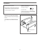
2. Identify the Frame Cover (54), and orient it as shown. Slide the Frame Cover onto the Frame (1), and press the posts on the Frame Cover into the indicated holes in the Frame. 2 81 Next, orient the Upright (2) as shown. While a second person holds the Upright near the Frame (1), connect the Upper Wire Harness (81) to the Lower Wire Harness (82). Avoid pinching the wires Tip: Avoid pinching the Wire Harnesses (81, 82).
4. Identify the Right Handrail (5), which is marked with an “R” on the underside. Orient the Right Handrail as shown. 4 Avoid pinching the Heart Rate Wires (92) While a second person holds the Right Handrail (5) near the Upright (2), tie the indicated wire tie to the Right Heart Rate Wire (92). Then, pull the other end of the wire tie upward out of the top of the Upright. 4 Wire Tie 80 62 2 92 5 62 80 See the inset drawing.
6. Using a small plastic bag to keep your fingers clean, apply a generous amount of the included grease to the right axle on the Upright (2). 6 Next, identify the Right Handlebar Leg (13), which is marked with an “R” sticker, and orient it as shown. 12 2 Slide the Right Handlebar Leg (13) onto the axle on the Upright (2). Attach the Right Handlebar Leg with an M10 x 20mm Screw (61) and an M10 Washer (64). 13 Attach the Left Handlebar Leg (12) in the same way. 7.
8. Apply a small amount of grease to the axle on the Left Pedal Arm (14). 8 Position the Left Handlebar Leg (12) as shown. Then, insert the Left Pedal Arm (14) into the Left Handlebar Leg. Attach the Left Pedal Arm with an M10 x 20mm Screw (61), a Pedal Axle Cover (39), and an M10 Washer (64). Do not overtighten the Screw; the Left Pedal Arm must pivot easily. 12 61 64 Grease 39 14 Attach the Right Pedal Arm (not shown) in the same way. 9.
10. Identify the Right Large Rail Cover (93), and orient it as shown. Press the Right Large Rail Cover into the Right Outer Shield (17). 10 Next, identify the Right Small Rail Cover (7), and orient it as shown. Press the Right Small Rail Cover into the Right Large Rail Cover (93) and into the Right Outer Shield (17). Attach the Left Large and Small Rail Covers (90, 6) in the same way. 16 90 93 6 7 17 11. Identify the Right Handlebar (11), which is marked with an “R” sticker.
. While a second person holds the Console (3) near the Upright (2), connect the four wires on the Console to the Upper Wire Harness (81), the two Heart Rate Wires (92, 116), and the Receiver Wire (109). Insert the excess wire into the Upright. 12 3 92 81 109 Tip: Avoid pinching the wires. Attach the Console (3) to the Upright (2) with four M4 x 16mm Screws (67). 13. Plug the Power Adapter (84) into the receptacle on the front of the elliptical.
HOW TO USE THE ELLIPTICAL HOW TO PLUG IN THE POWER ADAPTER HOW TO LEVEL THE ELLIPTICAL IMPORTANT: If the elliptical has been exposed to cold temperatures, allow it to warm to room temperature before you plug in the power adapter. If you do not do this, you may damage the console displays or other electronic components. If the elliptical rocks slightly on your floor during use, turn one or both of the leveling feet beneath the rear of the frame until the rocking motion is eliminated.
HOW TO EXERCISE ON THE ELLIPTICAL To mount the elliptical, hold the handlebars and step onto the pedal that is in the lower position. Then, step onto the other pedal. Push the pedals until they begin to move with a continuous motion. Note: The pedals can turn in either direction. It is recommended that you turn the pedals in the direction shown by the arrow; however, for variety, you can turn the pedals in the opposite direction.
CONSOLE DIAGRAM FEATURES OF THE CONSOLE The console also features an iFit Live mode that enables the console to communicate with your wireless network through an optional iFit Live module. With the iFit Live mode, you can download personalized workouts, create your own workouts, track your workout results, race against other runners, and access many other features. To purchase an iFit Live module at any time, go to www.iFit.com or call the telephone number on the front cover of this manual.
HOW TO ACTIVATE THE CONSOLE 4. Follow your progress with the display. The included power adapter must be used to operate the elliptical. See HOW TO PLUG IN THE POWER ADAPTER on page 13. When the power adapter is plugged in, the display will light and the console will be ready for use. The display can show the following workout information: HOW TO TURN OFF THE CONSOLE If the pedals do not move for several seconds, a tone will sound and the console will pause.
Press the Home button to exit the manual mode or a workout and return to the default menu (see HOW TO CHANGE CONSOLE SETTINGS on page 21 to set the default menu). If necessary, press the Home button again. Stride—This display mode will show the total number of strides you have pedaled. Time—When the manual mode is selected, this display mode will show the elapsed time. When a workout is selected, this display mode will show the time remaining in the workout.
HOW TO USE AN ONBOARD WORKOUT If the display does not show your heart rate, make sure that your hands are positioned as described. Be careful not to move your hands excessively or to squeeze the contacts tightly. For optimal performance, clean the contacts using a soft cloth; never use alcohol, abrasives, or chemicals to clean the contacts. 1. Begin pedaling or press any button on the console to turn on the console. See HOW TO ACTIVATE THE CONSOLE on page 16. 2. Select an onboard workout. 6.
During the workout, the profiles on the speed tab will show your progress. Profile The flashing segment of the profile represents the current segment of the workout. The height of the flashing segment indicates the target speed for the current segment. If the resistance level for the current segment is too high or too low, you can manually override the setting by pressing the Resistance buttons.
HOW TO USE AN IFIT LIVE WORKOUT When you select an iFit Live workout, the display will show the duration of the workout and the approximate number of calories you will burn. The display may also show the name of the workout. If you select a competition workout, the display may count down to the beginning of the race. You must have an iFit Live module to use an iFit Live workout. To purchase an iFit Live module at any time, go to www.iFit.com or call the telephone number on the front cover of this manual.
HOW TO USE THE SOUND SYSTEM The following settings can be viewed and changed when an iFit Live module is connected: To play music or audio books through the console sound system while you exercise, plug the included audio cable into the jack on the console and into a jack on your MP3 player or CD player; make sure that the audio cable is fully plugged in. Press the decrease button next to the Enter button to view the status of the personal trainer voice.
MAINTENANCE AND TROUBLESHOOTING Inspect and tighten all parts of the elliptical regularly. Replace any worn parts immediately. Next, locate the Reed Switch (86). Turn the Pulley (53) until a Magnet (88) is aligned with the Reed Switch. To clean the elliptical, use a damp cloth and a small amount of mild soap. IMPORTANT: To avoid damage to the console, keep liquids away from the console and keep the console out of direct sunlight.
EXERCISE GUIDELINES Burning Fat—To burn fat effectively, you must exercise at a low intensity level for a sustained period of time. During the first few minutes of exercise, your body uses carbohydrate calories for energy. Only after the first few minutes of exercise does your body begin to use stored fat calories for energy. If your goal is to burn fat, adjust the intensity of your exercise until your heart rate is near the lowest number in your training zone.
SUGGESTED STRETCHES The correct form for several basic stretches is shown at the right. Move slowly as you stretch—never bounce. 1. Toe Touch Stretch Stand with your knees bent slightly and slowly bend forward from your hips. Allow your back and shoulders to relax as you reach down toward your toes as far as possible. Hold for 15 counts, then relax. Repeat 3 times. Stretches: Hamstrings, back of knees and back. 1 2. Hamstring Stretch Sit with one leg extended.
NOTES 25
NOTES 26
PART LIST Key No. Qty. 1 2 3 4 5 6 7 8 9 10 11 12 13 14 15 16 17 18 19 20 21 22 23 24 25 26 27 28 29 30 31 32 33 34 35 36 37 38 39 40 41 42 43 44 45 46 1 1 1 1 1 1 1 2 1 1 1 1 1 1 1 1 1 1 1 1 1 1 1 1 1 2 2 2 2 1 2 1 4 4 4 2 4 2 2 1 1 1 1 8 6 2 Model No. NTEL08911.0 R0511A Description Key No. Qty.
Key No. Qty. 93 94 95 96 97 98 99 100 101 102 103 104 105 106 107 1 2 1 1 1 13 1 1 2 2 1 2 1 1 1 Description Key No. Qty. Right Large Rail Cover Handle Bottom M5 x 7mm Screw Magnet Bracket Bolt Pivot Screw M4 x 16mm Bright Screw M3.
61 6 4 28 61 26 79 113 91 111 36 61 90 78 113 94 35 78 62 67 67 75 79 67 60 27 117 78 80 80 35 29 98 62 112 8 22 14 60 67 98 38 98 49 68 10 67 98 68 31 98 114 61 56 33 64 67 98 61 34 67 39 64 37 16 73 67 37 59 64 61 12 33 34 67 67 74 85 67 67 74 67 24 67 18 67 20 67 73 67 EXPLODED DRAWING A Model No. NTEL08911.
36 30 78 118 78 78 109 9 74 67 98 67 74 21 98 98 25 15 64 98 98 56 33 61 114 34 79 98 37 59 13 61 37 38 61 79 39 61 64 49 33 64 34 29 60 67 67 35 11 31 8 67 35 68 23 60 67 67 75 26 27 28 111 EXPLODED DRAWING B Model No. NTEL08911.
52 50 59 65 66 95 99 57 59 50 52 59 58 103 97 102 52 30 61 84 46 44 107 63 50 45 72 101 79 54 44 45 44 108 100 67 98 72 44 46 45 44 44 45 43 83 44 104 105 50 89 47 45 70 71 76 77 104 48 42 59 96 51 86 61 106 1 79 69 40 48 45 47 71 32 44 52 115 65 87 67 101 55 115 41 3 88 51 19 73 67 82 116 66 88 67 69 92 67 81 62 110 59 61 67 7 67 53 62 67 5 2 17 73 59 67 80 113 93 94 67 62 61 91 67 80 67 67 11
ORDERING REPLACEMENT PARTS To order replacement parts, please see the front cover of this manual.