GP Series Portable Generator COMMERCIAL • INDUSTRIAL • RESIDENTIAL Owner’s Manual • SAFETY • ASSEMBLY • OPERATION • TROUBLESHOOTING • WARRANTY AUTHORIZED DEALER SUPPORT: www.generac.
Table of Contents OWNER'S MANUAL Introduction..............................................................................1 Read This Manual Thoroughly .................................................1 Safety Rules ............................................................................2 Standards Index ...............................................................................3 Section 1 – General Information ..............................................4 1.1 1.2 Unpacking....................
INTRODUCTION Thank you for purchasing this model by Generac Power Systems, Inc.® This model is a compact, high performance, air-cooled, engine driven generator designed to supply electrical power to operate electrical loads where no utility power is available or in place of utility due to a power outage. READ THIS MANUAL THOROUGHLY DANGER a generator indoors WILL KILL YOU IN Using MINUTES. Exhaust contains carbon monoxide, a poison gas you cannot see or smell.
IMPORTANT SAFETY INSTRUCTIONS SAVE THESE INSTRUCTIONS – The manufacturer suggests that these rules for safe operation be copied and posted near the unit's installation site. Safety should be stressed to all operators and potential operators of this equipment. • Never start or stop the unit with electrical loads connected to receptacles AND with connected devices turned ON. Start the engine and let it stabilize before connecting electrical loads.
IMPORTANT SAFETY INSTRUCTIONS ELECTRICAL HAZARDS EXPLOSION HAZARDS • All generators covered by this manual produce dangerous electrical voltages and can cause fatal electrical shock. Utility power delivers extremely high and dangerous voltages as does the generator when it is in operation. Avoid contact with bare wires, terminals, connections, etc., while the unit is running. Ensure all appropriate covers, guards and barriers are in place before operating the generator.
Section 1 – General Information 1.1 UNPACKING 1.2 • Set the palleted carton on a rigid flat surface. • Remove staples along bottom of carton that fasten carton to pallet. Open carton from top. • Remove all packaging material. ASSEMBLY The generator requires some assembly prior to using it. If problems arise when assembling the generator, please call the Generator Helpline at 1-888-436-3722. 1.2.1 ASSEMBLING THE WHEEL KIT • Remove separate accessory box. • Lift carton off the generator.
Section 1 - General Information Figure 2 - Handle Assembly 1.2.3 BATTERY CONNECTION • The battery shipped with the generator has been provided fully charged. Caution must be taken when connecting the battery. NOTE: Figure 3 - Battery Connections Negative Cable Positive Cable A battery may lose some of it’s charge when not in use for prolonged periods of time. • Cut the tie wrap cable holding the RED and BLACK battery cables to the stator.
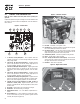
Section 2 – Operation 2.1 KNOW THE GENERATOR Figure 5 - Generator Controls Read the Owner’s Manual and Safety Rules before operating this generator. Compare the generator to Figures 4 through 6 to become familiarized with the locations of various controls and adjustments. Save this manual for future reference. 11 7 Figure 4 - Control Panel 10 1 17 13 2 3 12 15 4 6 1.
Section 2 – Operation 2.2 HOURMETER The Hourmeter tracks hours of operation for scheduled maintenance: There will be a one time break in "CHG OIL" message that flashes with the elapsed time in hours and tenths after the first 30 hours of operation. 2.3.2 120 VAC, 20 AMP, GFCI RECEPTACLE This unit is equipped with a ground fault circuit interrupter (GFCI). This device meets applicable federal, state and local codes (Figure 8).
Section 2 – Operation 2.3.3 120 VAC, 30 AMP RECEPTACLE Figure 11 - 12 Volt DC, 10 Amp Receptacle Use a NEMA L5-30 plug with this receptacle. Connect a 3-wire cord set rated for 125 Volts AC at 30 Amps (or greater) to the plug (Figure 9). Figure 9 - 120 VAC, 30 Amp Receptacle 2.3.6 120/240 VAC, 50 AMP RECEPTACLE Use a NEMA 14-50 plug with this receptacle. Connect a 4-wire cord set rated for 250 Volts AC at 50 Amps to the plug (Figure 12).
Section 2 – Operation Figure 13 - Grounding the Generator 1. 2. Figure the watts needed to start the largest motor. Add to that figure the running watts of all other connected loads. The Wattage Reference Guide is provided to assist in determining how many items the generator can operate at one time. NOTE: Generator Ground Lug All figures are approximate. See data label on appliance for wattage requirements. 2.
Section 2 – Operation *Table Saw (10") . . . . . . . . . . . . . . . . . . . . . . . . . . . . .1750 to 2000 Television . . . . . . . . . . . . . . . . . . . . . . . . . . . . . . . . . . . . .200 to 500 Toaster . . . . . . . . . . . . . . . . . . . . . . . . . . . . . . . . . . . . .1000 to 1650 Weed Trimmer . . . . . . . . . . . . . . . . . . . . . . . . . . . . . . . . . . . . . . 500 * Allow 3 times the listed watts for starting these devices. 2.
Section 2 – Operation • Open the fuel shut-off valve (Figure 15). Figure 15 - Fuel Shut-off Valve • To start engine, press and hold the Start/Run/Stop switch in the “Start” position. The engine will crank and attempt to start. When the engine starts, release the switch to the run position. • When the engine starts, move choke knob to “1/2 Choke” position until the engine runs smoothly and then fully in to the “Run” position.
Section 3 — Maintenance 2.12.1 INITIAL START-UP A delay built into the low oil shutdown system allows oil pressure to build during starting. The delay allows the engine to run for about 10 seconds before sensing oil pressure. 2.12.2 SENSING LOW OIL PRESSURE If the system senses low oil pressure during operation, the engine shuts down. 2.12.3 RESTARTING If trying to restart the engine within 10 seconds after it shuts down, the engine may NOT start. The system needs five (5) to 10 seconds to reset.
Section 3 — Maintenance 3.2.2 ENGINE SPECIFICATIONS Rated Horsepower @ 3600 RPM 30 Displacement 992cc Spark Plug Type Champion RC14YC or Equivalent Spark Plug Gap 0.040 inch or (1.01 mm) Gasoline Capacity 16 U.S. gallons Oil Type Summer – SAE 30, Winter – 5W-30 Synthetic or 10W-30 Oil Capacity w/ Filter Change = 1.7 Qts., w/o Filter Change = 1.4 Qts. Run Time/Fuel Consumption-1/2 Load 10 Hours / 1.6 gallons per hour 3.
Section 3 — Maintenance 3.3.6 REPLACING THE SPARK PLUGS To clean or replace paper air filter: Use Champion RC14YC spark plug or equivalent. The correct air gap is 1.01 mm (0.040 in.). Replace the plugs once each year. This will help the engine start easier and run better. • Remove air cleaner cover; then remove foam pre-filter (service if necessary) and remove paper filter. 1. 2. Stop the engine and pull the spark plug wire off of the spark plug.
Section 3 — Maintenance 3.6 ADJUSTING VALVE CLEARANCE After the first 50 hours of operation, check the valve clearance in the engine and adjust if necessary. Important: If feeling uncomfortable about doing this procedure or the proper tools are not available, please take the generator to the nearest service center to have the valve clearance adjusted. This is a very important step to insure longest life for the engine. To check valve clearance: • Make sure the engine is at room temperature (60° - 80° F).
Section 3 — Maintenance 3.9 spray from spark plug holes when cranking Avoid engine. • Install and tighten spark plugs. Do not connect spark plug wires. • Clean the generator outer surfaces. Check that cooling air slots and openings on generator are open and unobstructed. • Store the unit in a clean, dry place. OTHER STORAGE TIPS • Do not store gasoline from one season to another. • Replace the gasoline can if it starts to rust.
Section 4 — Troubleshooting 4.1 TROUBLESHOOTING GUIDE PROBLEM CAUSE CORRECTION Engine is running, but no AC output is available. 1. 2. 3. 4. Circuit breaker is open. Poor connection or defective cord set. Connected device is bad. Fault in generator. 1. Reset circuit breaker. 2. Check and repair. 3. Connect another device that is in good condition. 4. Contact Authorized Service Facility. Engine runs good but bogs down when loads are connected. 1. 2. 3. 4. Short circuit in a connected load.
Section 5 – Warranty CALIFORNIA EMISSION CONTROL WARRANTY STATEMENT YOUR WARRANTY RIGHTS AND OBLIGATIONS The California Air Resources Board (CARB) and Generac Power Systems, Inc. (Generac) are pleased to explain the Emission Control System warranty on your new engine. In California, new off-road Large Spark-Ignition (LSI) engines must be designed, built and equipped to meet the state's stringent anti-smog standards.
Section 5 – Warranty EMISSION CONTROL SYSTEM WARRANTY Emission Control System Warranty (ECS warranty) for 2001 and later model year LSI engines: (a) Applicability: This warranty shall apply to 2001 and later model year engines. The ECS Warranty period shall begin on the date the new engine or equipment is purchased by/delivered to its original, end-use purchaser/owner and shall continue for 24 consecutive months thereafter.
Section 5 – Warranty GENERAC POWER SYSTEMS “TWO YEAR” LIMITED WARRANTY FOR GP SERIES PORTABLE GENERATORS For a period of two years from the date of original sale, Generac Power Systems, Inc. (Generac) warrants its GP Series generators will be free from defects in materials and workmanship for the items and period set forth below.