
User manual

SeaSTAR 3100LRS USER MANUAL
Issue 1.0 08/02
9
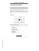
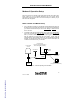
Antenna
Antenna connection is made via a 5 metre RG58 low loss cable,
which is terminated with a standard TNC 50-ohm male connector.
If two antennae are supplied, each antenna will have its own cable.
An antenna unit has an internal LNA (low noise amplifier) which is typically
powered by 12V DC. When the 3100LRS is powered up, this voltage is present
at the antenna socket on the rear panel. Therefore, care must be taken not to
connect or disconnect an antenna when power is on.
Data
The Data port is a standard DB9 female socket. Data logging can be carried
out by plugging a Psion data logger into this port. A laptop computer may also
be plugged into the Data port for data logging and position information retrieval.
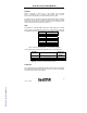
Pin Number Signal
1
2 TXD2
3 RXD2
4
5 GND2
6
7
8
9 ANT STEERING*
Table 1 Data Port Pin Assignment (* no connection by default)
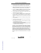
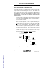
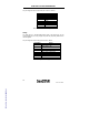
A special Data cable is supplied, terminated as shown in the Figure below.
DB9 Male
Pin number
2 metre cable
DB9 Female
Pin
number
2 --------------- 2
3 --------------- 3
5 --------------- 5
Warning: Do NOT use standard RS232 cables.
Command
The Command port is a standard DB9 female socket. Receiver configuration
(Fugro SeaSTAR 3000LCE board) can be carried out via this port by plugging
in a laptop computer with ‘Toolkit’ software.
FSPAS Ref.: B31005102PMBRA0