
Installation Guide
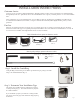

Step 3: Mark holes for installation
An installation template has been provided to help position your pilot
holes. To use the template, temporarily attach your template to your
mounting surface (Fig. D ) and drill your pilot holes in the four shaded
areas as shown in Figure E. Remove the template before moving to the
next step.
Figure D
Figure E
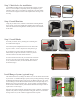
Step 4: Install Brackets
Using the provided screws, install the Crank Bracket and Plug Bracket
(Fig F and G). Note: The Crank Bracket should be placed on the right
side of the shade and the Plug Bracket should be placed on the left side
of the shade.
Step 5: Install Shade
To install your shade, start by inserting the Crank Plug into
the Crank Bracket (Fig H).
Next rotate/open the Plug Bracket and insert the shade, mak-
ing sure to hear a “click” as the pin locks into place (Fig I).
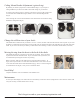
If your shade moves side-to side after installation, we rec-
ommend that you adjust the brackets to reduce any lateral
movement between the shade and the brackets.
To reduce lateral movement, roll your shade down and loosen
the screws on both of your brackets slightly. Push the brack-
ets in, (towards each other), to reduce the distance between
the brackets (Fig J).
Figure F
Figure G
Figure H Figure I
Open Bracket
Push brackets in to
reduce slack
Figure K
Install Bungee System (optional step)
The shade includes two (2) Bungee Tie Downs to secure the bottom of both sides
of your shade. To install the Bungee System, start by feeding the Bungee through
the Bottom Tube Plugs located at each end of your Bottom Tube (Fig. K). Then
insert the Bungee into the Hook and drill the Hook into a wall/post using one (1)
Bracket Screw from your hardware box. To prevent fabric stretching/damage,
hooks should be installed directly underneath the Bottom Tube Plugs so there is
equal tension on each bungee.
Important: Your shade should be rolled up during windy conditions. The Bungee
System is only eective in light wind. When using your shade, we recommend
leaving at least one (1) roll of fabric wrapped around the top tube.
Figure J
Pg. 2