
User's Manual


Technical description
9
2 Technical description
2.1 Design
2.1.1 Controls and indicators
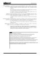
The following figure shows the loggers’ ON/OFF switch and control lamp.
Item
Description
On/Off contact area
I/O control lamp
Here you find some possible states of the logger’s control lamp .
LED status Description
green (1 x per second) logger is switched on
red (regularly) logger is sampling (flashing is according to log interval)
blue (1x each 10 seconds)
logger is checking for radio signal
blue (rapidly) during data transfer via radio
blue (constantly) during connection to radio signal
green (unsteady) GSM operations are done, data are transmitted
green (constantly) logger is dialing in to GSM network
red (constantly) Error !!
• common GSM error, e.g. powering up modem failed,no
SIM card detected, dial in unsuccessful, error during ftp
data transfer - (LED turns off when modem was
successfully turned down)
• wrong PIN code - (flashing red 3x before turning on
constantly)
• SIM-card blocked, PUK needed - (flashing white 3x
before turning on constantly)
Control lamp states