
Operation Manual


6. Inbetriebnahme
Zusammenbau des Bürststaubsaugers
Das Filtergehäuse(20) in senkrechter
Position vorsichtig über das Gelenk(21)
und den Gelenkarm(46) stecken und
nach unten drücken, bis die Entriege-
lungstaste(12) einrastet.
Zur Demontage die Entriegelungsta-
ste(12) drücken und das Filtergehäu-
se(20) durch Ziehen von dem Geräte-
fuß(9) trennen.
Den Stecker(33) der Anschlussleitung
am Gelenk(21) einstecken. Hierbei un-
bedingt darauf achten, dass der Stek-
ker hinter Kante(20) gehalten wird.
Die Leitung anschließend an der In-
nenseite der Halterung für das Tele-
skoprohr und am Gehäuse in die vor-
gesehenen Halterungen(22) einlegen.
1 Griff
2 Stiel
3 Sicherungsring
4 Filtertütenanzeige
5 Handgriff (des Teleskopsaugrohrs)
6 Teleskopschlauch
7 Teleskoprohr
8 Griffmulde
9 Gerätefuß mit Bürste
10 Ein-/Aus-Schalter
11 Regelungsschalter Bürste
12 Entriegelungstaste
13 Anschlussleitung
14 Tragegriff
15 Deckelschloss
16 Kabelhalter
17 Fugendüse
18 Polsterdüse
19 Rastpedal
Bitte lesen Sie zuerst gründlich diese
Gebrauchsanweisung. Bitte beachten
Sie unbedingt die Sicherheitshinwei-
se.
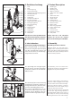
6. Assembly
Assembling the Vacuum Cleaner
Carefully place the dust bag hous-
ing(20) in the vertical position and fit
it over the swivel neck(21) and support
lever(46) of the power head(9) until the
release button(12) locks.
To dismantle, press the release but-
ton(12) and remove the dust bag hous-
ing(20) from the power head(9).
To fit the mains cable to the machine,
push the rubber plug(33) of the cable
into the socket on the swivel neck(21)
when the vacuum cleaner is assem-
bled. Please ensure the rubber plug is
fully inserted into the socket.
Fit the mains cable into the groove(22)
in the dust bag housing located in
the attachment wand recess, then to
the clamps on the top of the dust bag
housing and on the rear of the handle.
1 Handle grip
2 Handle tube
3 Retaining ring
4 Bag full indicator
5 Attachment tube handle
6 Hose
7 Attachment tube
8 Recessed grip
9 Power head
10 On/Off switch
11 Pile adjustment knob
12 Release button
13 Mains cable
14 Rear carrying handle
15 Cover release latch
16 Cable hook
17 Crevice nozzle
18 Upholstery nozzle
19 Foot pedal
Please read all of this instruction
manual. Do not use the machine
before understanding the CAUTIONS.
5. Product Description
5. Gerätebeschreibung
CHECK
BRUSH
ON/OFF
2
2
PUSH
1
10
2
7
3
4
11
8
9
5
13
6
14
15
16
19
17
18
12
2
CHECK
BRUSH
ON/OFF
12
CHECK
BRUSH
ON/OFF
2
7
21
6
17
18
20
46
2
22
22
35
33
20
7