
Owner`s manual


6
IDENTIFICATION OF PARTS
ASSEMBLY
1. Handle grip
2. On/Off switch
3. Handle assembly
4. Retaining ring
5. Cover release flap
6. Dust bag housing
7. Front cover
8. Housing release button
9. Power head with brush
10. Cable (cord)
11. Attachment tube handle
12. Attachment hose
13. Carrying handle
1
4. Cable (cord) hook
15. Attachment tube (active wand)
16. Crevice nozzle
17. Upholstery nozzle
18. Pile adjustment knob
19. Foot pedal
2
0. Swivel neck
21. Support lever
22. Handle release catch
23. Projection tab
24. Connecting tube
25. Dusting brush clamp
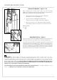
Place the power head (9) on the floor with the swivel
neck (20) and the support lever (21) upright. Hold the
dust bag housing (6) vertically and place it over the
swivel neck and support lever. Push firmly and evenly
down so that the housing release button (8) snaps out-
ward to its “locked” position.
Slide the dusting brush clamp (25) onto the handle
tube (3) and tighten the screw. The handle of the dust-
ing brush (26) will now snap into the clamp.
To insert the handle tube (3) into the housing, lift the
catch (22), slide the handle in, making sure that the
handle is all the way in and cannot go any further.
Push the catch (22) down to lock handle in place. If the
handle is not pushed fully down, the vacuum will not
work.
Push the black end of the attachment hose (12) into
the connecting tube (24) so that it clicks into place.
Insert the attachment tube (15) into the swivel neck
opening and seat the handle (11) over the projection
tab (23).
Attach
dusting brush
clamp with
screw
25
26
26
17
16
25
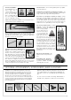
Optional Attachments
41. Wall and floor brush - Part # 1325 HG
42. Turbo brush for stairs - Part # 6179 DA
43. Radiator brush - Part # 1496 DG
44. Extension hose (9’3”) - Part # 1495 AM
45. Straight tube - Part # 1084 HG
46. Flat upholstery nozzle - Part # 1090 HG
Also available for odor control - the combined
micro/charcoal filter - Part # 5425 AM
45
Standard Attachments
16. Crevice nozzle
17. Upholstery nozzle
25. Dusting brush clamp
26. Dusting brush
42
43
46
44
41
NOTE: All illustra-
tions shown in this
manual represent
the G1 model except
where part numbers
and instructions are
different for each
model. In those
instances, illustra-
tions for both the G1
and G2 will be
shown.