SEC SEC America Corp Model 7058 DC-DC Converter Rev 4 Owner's Manual June 3, 2018
TABLE OF CONTENTS page I Introduction 1 II Installation 2.1 Mounting 2.2 Connections 2.3 Methods of Converter Activation 1 1 1 2 III Performance Characteristics and Indicator Lights 3 IV Internal Adjustment of Output Voltage 4.
I Introduction Model 7058 is shipped in fully assembled form. The installer should locate a bag containing a quantity of (4) blade terminals intended for use with the I/O cabling to be used with the unit. After removal of the unit from its packaging it should be verified that it has suffered no damage in shipment. It is very important to follow the instructions of this manual to ensure proper connection and mounting. Model 7058 is a high power 12 Volt to a maximum of 58.
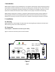
Prior to Main Input Power Connections: The 7058 comes supplied with 4 blade terminals intended for crimping on to #2 AWG multi‐stranded battery cable. It is important to utilize these terminals in order to realize reliable high current capacity connections between the terminal block and input/output cables. Prior to hook up to the vehicle power source, the buttons on the two circuit breakers shown in Figure 1 should be pulled out into the OFF position.
III Performance Characteristics and Indicator Light Functions Once 7058 is properly connected, it is ready for activation. A microprocessor controls the 7058 performance and protection functions: ON STATE FUNCTIONS Output Voltage Cycles A) Upon initial turn on, the unit comes on with a charging voltage of 58.4 VDC limited to 30A. This state is discernible by the illumination of the green light (high charge indicator).
Table 1 shows the correspondence between indicator light states and the state of unit’s operation: GREEN AMBER STATE OFF ON Charging Off ON OFF Charge On OFF OFF FLASHING Low Input Voltage OFF Unit Off Table 1 IV Battery Type Selection Model 7058 is preprogrammed at the factory to be usable with batteries of 2 distinctive chemistries – 16 cell Lithium Iron Phosphate and 48V Lead Acid (AGM).
IV Internal Adjustment of Output Voltage There should be no need for any adjustment provided the unit is used for its intended application. In the event that there is a need to alter the output voltage, use the following procedure: Varying the adjustments of the Model 7058 requires the technician to have a stable DC power supply variable from at least 20 VDC to 30 VDC with a current capacity of at least 3A. This adjustment should be conducted with no load on the charger.
V Warranty and Repair Should your investigations indicate that your new Model 7058 is defective or damaged and your unit is still under warranty, contact SEC America Corp. at 802‐865‐8388 and obtain return merchandise authorization for credit or exchange. If the warranty period has expired or if the warranty has been violated due to operator error or misuse, call: SEC America, Corp, Repair Department, at 802‐865‐8388 or fax SEC America Corp.
LIMITED WARRANTY We warrant each instrument, sold by us, or our authorized agents, to be free from defects in material and workmanship and that it will perform within applicable specifications for a period of two years after original shipment.
VI Mechanical Drawing Page 8
VII Electrical Specifications: Output Voltage: Output Voltage Adjust Range Continuous Max Load Amps: 58.4V Charge Nominal (16 cell LiFePO4) 47.5 VDC to 56.0 VDC (float) 30 ADC @ 40C ambient (Input 12.5 VDC) 22 ADC @ 60C ambient Maximum Power Dissipation: Maximum Input Current: Overload Protection: 110 Watts @ Full Load (30A, 58.
SEC SEC America Corp