OPERATING INSTRUCTIONS for vinyl cutters Secabo C30III, C60III and C120III Congratulations on purchasing a Secabo vinyl cutter! Please read these operating instructions thoroughly to ensure that you can start production with your vinyl cutter without problems. Reproduction of these operating instructions in any form requires written approval of Secabo GmbH. We reserve all rights to change technical data and product features without prior notice. Not liable for printing errors.
Table of Contents 1 Safety Precautions ................................................................ ................................................................................... ................................................... 2 2 Items Included ................................................................ ........................................................................................ ........................................................ 3 3 Layout of StandStand-UpUp-Base...
1 Safety Precautions Please read these instructions and safety precautions carefully before using your vinyl cutter for the first time! • Do not place any magnetic objects in the vicinity of the cutting head; otherwise uniform contact pressure is not ensured. • Do not remove the connection cable to the computer while plotting is in progress. • Relieve the pressure on the pressure rollers when not in use by moving the pressure lever up.
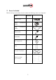
2 Items Included Before starting work, please check whether the following items are all present: Item Quantity Power cable 1 Serial cable connection 1 USB cable connection 1 Bladeholder 1 Penholder 1 45° drag knife 3 Pens 2 Secabo FlexiStarter 1 Stand-up-base 1 (not with C30III) 3
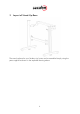
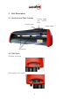
3 Layout of Stand-Up-Base The stand-up base for your Secabo vinyl cutter can be assembled simply using the parts supplied as shown in the exploded drawing above.
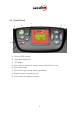
4 Unit Description 4.1 Unit Parts and Their Function Cutting head with LAPOS Laser Control panel Blade Holder Grid rollers 4.
4.
5 Starting Up Appliance and Software Attention! Please note that you need to install FlexiStarter first to ensure a smooth installation and complete configuration of your Secabo vinyl cutter. 5.1 Installation Secabo FlexiStarter Version 8.6 of the FlexiStarter cutting software with USB-dongle is supplied with your Secabo vinyl cutter. To control the vinyl cutter with your PC, install the software as described below: 5.1.1 Version 8.
• After installing, connect the vinyl cutter to the USB interface on your PC using the USB cable provided. Windows then indicates that new hardware components have been recognized and shows when the installation is completed. • To determine the number assigned to the new interface, it is necessary to call the Windows Device Manager. For this purpose, click on Workplace with the right mouse key and select Properties. Then select the Hardware tab in the window which opens and click Device Manger.
• In FlexiStarter under Edit / Settings / Tools / Plotting and cutting, remove the check mark in front of Connect to local Production Manager over TCP/IP (applies only for users on local PC). CAUTION! These settings must be made before starting a plotting job; they do not become effective for plotting jobs already active! 5.4 Starting Up Appliance Ensure that sufficient space is present for the vinyl transport in front of and in back of the unit.
5.6 Inserting the Blade Holder • First turn the clamping screw for the blade holder on the cutting head until it is open wide enough. • Then insert the blade holder from the top and press down against the stop in the hole on the right side and retighten the clamping screw Blade holder Knurled screw 5.7 Inserting cutting vinyl • Always insert the material to be printed into the unit from the rear. • Pull the vinyl up to the cutting bar in order to correctly set the zero point.
5.8 Cutting Test • To perform the cutting test in the offline mode, press the Test button; the plotter then cuts a rectangle in the inserted vinyl at the currently stored zero point. • You can check the adjustment of the blade holder as well as the contact pressure with this cutting test. The material inserted should be cut cleanly and straight during the cutting test; the backing material should not be damaged.
6 Settings and Operation 6.1 Online/Offline After switching on the unit a reset is performed and the unit switches to the online mode. You can switch back and forth between the online and offline mode by pressing the Online button on the control panel. During the cutting operation, the vinyl cutter must generally be in the online mode, to change the configuration settings, the unit must be offline. Online-Status Online Offline-Status Offline 6.
6.4 Changing You can make the following changes in the online mode by pressing the corresponding buttons: Increase speed Reduce speed Increase pressure Reduce pressure The cutting speed and contact pressure cannot be changed while a plotting job is in progress. 6.5 Repeat Function After conclusion of a job it can be repeated without having to transfer the data from the computer again. For this purpose ensure that the vinyl cutter is in the offline mode and press the Repeat key.
6.6 Other Settings It is possible to scroll through other configuration menus in the offline mode by pressing the menu key a number of times. In the settings menu it is possible to adjust the idle speed of the cutting head (Ur), as well as the Baud rate (Br). The Baud rate set must be identical with the Baud rate set on the computer. This value must be set to 38400. The vinyl cutter can be calibrated correctly in the scaling menu (Set Per).
7 LAPOS (just C60III and C120III as of Model 11/08) LAPOS is a system for positioning printable media in your CIII cutting plotter so that you can cut the printed elements in the designated contour without offset and free from distortion. The installation as well as the application of LAPOS is explained in the following steps. 7.1 One-time Calibration of LAPOS Before you can do the first contour cut you have to calibrate LAPOS once in connection with the FlexiStarter.
1mm“ so that the cut elements do not receive a white border later on. While calibrating it is best to use the value “0 mm“. Please confirm your entry by clicking the green check mark on the bottom right in the menu. • Now choose the menu “Effects“ – “Contour cutting mark“. • Now you can choose whether two cutting marks horizontally or vertically shall be set. With small prints two marks are enough as they can be read in faster. With larger printed sheets 4 marks should be used to reach a higher accuracy.
• Now please click on the printer symbol in the top menu to print the object according to the set marks with a printer of your choice. Please be careful that the print is not scaled by the printer driver. • Please place the print in the cutting plotter (if using paper its best on a plotting pad) so that the set marks are located on the left above the cutting head. • Now choose the contour cutting function from the top menu.
• In the following window click on “Send“. • Please confirm here with “OK“. • A laser diode is now going to be activated on your Secabo cutting plotter. With help of the arrow keys lead this to the centre of the right cutting mark (No. “1”). Please note that you must push one of the arrow keys within several seconds to avoid the cutting plotter leaving the LAPOS modus automatically.
• When the laser is exactly in the middle of the cutting marks confirm with “Ok” and continue the procedure with the second cutting mark.
• As soon as you clicked “OK“ in the following window, the cutting plotter will begin to plot the contour (with a distinct offset). During the calibrating it is recommended to use a plot pen and to change to the cutting head at a later time. • Now remove the plot and measure the offset in both directions as shown in the following picture. • Now you just have to enter the calculated offset in the corresponding menu in the FlexiStarter, so that the contours are always cut correctly.
• Now you can repeat the contour cut by repeating all steps starting off with „Send“ in the menu „Contour cutting”. Please look out for the offset values if applicable. 7.2 Application of LAPOS • After the successful calibration you can use LAPOS by pursuing the steps in chapter 7.1 though, without measuring and entering the offset values again. • Instead of the above used rectangle you can import any type of object and graphic into the FlexiStarter and cut them perfectly outlined.
8 Drag knifes Drag knifes are sensitive, sharp and dangerous precision tools. • Always keep the blades away from children! • Exercise care when handling blades to prevent injuries. • Treat the cutting blades carefully and always store them with the associated protective cap when not in use. If the tip of a blade hits against a hard material such as glass or stone, tiny chips can be broken out of the tip rendering the blade unusable.
9 Technical Data Model C30III C60III Type Desktop unit Unit including stand-up base and LAPOS Unit including standup base and LAPOS Max. medium width 415mm 720mm 1300mm Max. cutting width 305mm 610mm 1220mm Connections RS232C, USB Display Back-lighted, 4-line LCD display Plotter languages HP-GL, DMPL Memory Unit has 1MB internal memory Max. speed 600mm/s Max. medium thickness 1mm Contact pressure 50g – 500g Mechanical resolution 0.025mm Repetition accuracy < ± 0.
10 Troubleshooting The cutting plotter can no longer be accessed after a Windows update Possible causes: Windows regularly updates existing device drivers on your computer. During this process, the Secabo driver is replaced by a seemingly newer version which does not work. To manually undo this update, right-click My Computer and select Properties. You are now in the System Properties window. Select the Hardware tab and then Device Manager. Under Ports (COM & LPT), select your device (e.g.
Straight lines are cut zigzag Possible causes: Blade adjustment and/or contact pressure incorrect and should be checked. Curves are not cut properlay Possible causes: The curve quality setting in the job standard settings in the production manager is not set to high.
Konformitätserklärung Statement of Conformity Hiermit erklären wir in alleiniger Verantwortung, dass das unter „9. Technische Daten“ genannte Produkt mit den Bestimmungen der folgenden EG-Richtlinien und Normen übereinstimmt: We herewith declare under sole responsibility that the under „9.