
User Guide


SECO-LARM ELECTROMAGNETIC LOCK
SECO-LARM U.S.A., Inc. 5
7. Put a rubber washer between the two metal washers,
and place them over the armature screw between
the armature plate and the door. This allows the
plate to pivot around the screw to compensate for
door misalignment.
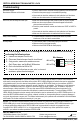
9. Screw the two short self-tapping screws through the mounting plate’s slotted holes, but do not over-tighten them.
Keeping them loose will allow for adjustment of the plate left or right so that the mounting plate and the armature
plate form a 90-degree angle. See the diagram below.
8. Tighten the armature screw enough so that the
armature plate can withstand a break-in attempt, but
loose enough so that the armature plate can pivot
slightly. Make sure the anti-spin guide pins are in the
two guide pin holes.
Mounting Plate
Armature Plate
90
The rubber washer will be
sandwiched between the
two metal washers.
Armature
screw
Guide pins
6. Depending on the type of door being protected, drill holes according to the diagrams below:
Hollow Metal Door
Solid Core Door
Reinforced Door
1/4” (6.8mm) for M8x1.25 thread
Drill a 5/16” (8mm) dia. hole through the
armature-plate side of the door for the
armature screw. Then drill a 5/8” (16mm)
dia. hole for sexnut screw on the
opposite side of the door.
Drill an 5/16” (8mm) dia. hole on the
door for the armature screw, and drill a
1/2” (12.7mm) dia. and 1” (25mm) deep
hole for the sexnut screw.
Drill a 1/4” (6.8mm)
dia. and 1” (25mm)
deep hole, tap for
M8x1.25 thread.
Tip: Use a thread-locking compound
on the armature screw to ensure
a long-lasting installation.
Metal
washers
5/8” (16mm)
5/16” (8mm)
1/2” (12 .7mm)
5/16” (8mm)
300-lb and 600-lb
mounting plate
300-lb mounting plate