
User Manual


ENFORCER Curtain Sensors
SECO-LARM U.S.A., Inc. 5
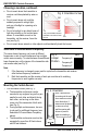
Run four wires (2x power and 2x alarm signal) from
the alarm control panel to the receiver of the curtain
sensor. Shielded cable is strongly suggested. See
Table 1 to the right for maximum wire length. Two
power wires must also be run to the transmitter.
It may be more convenient to connect the transmitter’s two power wires to the receiver’s power
wires. In this case, run six wires to the receiver: two wires to the power source, two for the alarm
signal, and two to the transmitter.
Note:
1. If burying the wires is required, make sure to run them through electrical conduit.
Shielded cable is strongly suggested.
2. If the wires are run along the wall, using an armored cable is strongly suggested.
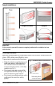
2. Mount the transmitter and the receiver so that the
surface-mounted wires do not come out from above
the units. This is to prevent water from entering via
the wire holes. If this is unavoidable, use silicone to
completely cover the area where the wires come out
the holes to prevent water from entering (see Fig. 4).
3. Once a suitable mounting location has been found,
remove the covers of the end caps (see Fig. 5), and
pull the tamper buttons out of the end caps (one per
transmitter or receiver) and locate the mounting holes.
Using these holes as a template, mark their location on the wall with a pencil.
4. Connect the wires (see Figs. 6 and 7) before permanently mounting the units to the wall.
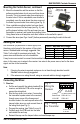
Fig. 5:
End
Cap
Cover
Plastic cap
hiding screw
Screw
Tamper Button
1. Receiver:
a. Pull the end cap with the red wire leads off the
receiver, and slide the PCB out far enough to
expose the wiring block.
b. Run the four wires (or six wires, if connecting
the transmitter’s power wires to the receiver)
through one or more of the three ground
knockout holes in the end cap near where the
tamper button wires run, and connect them to
the wiring block (see Fig. 6).
c. Program the receiver (see Table 2 on pg. 6).
d. Carefully push the PCB back into the case
and reinsert the end cap.
e. Reinsert the cap over the tamper button and small tamper cap.
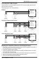
To Alarm Control Panel
12~24 VDC
Fig. 7: Wiring
the Transmitter
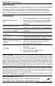
Running the Wires:
Table 1: Maximum Wire Length
Voltage
Gauge
Max. length
12VDC
AWG 22
1800’ (550m)
12VDC
AWG 20
2600’ (800m)
24VDC
AWG 22
2600’ (800m)
24VDC
AWG 20
3900’ (1200m)
Mounting the Curtain Sensor, continued:
Connecting the Wires:
Fig. 6:
Wiring the
Receiver
To Alarm
Control Panel
12~24 VDC
To Alarm Control Panel
COM + N.O. or
COM + N.C.
}
COM
N.C.
N.O.