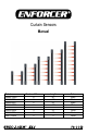
Curtain Sensors Manual Model E-9680-10B25 E-9660-8B25 E-9644-6B25 E-9644-6W25 E-9622-4B25 E-9622-4W25 E-9611-2B25 E-9611-2W25 Number of Beams 10 8 6 6 4 4 2 2 Length 80” 60” 44” 44” 22” 22” 11” 11” Color Black Black Black White Black White Black White
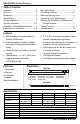
ENFORCER Curtain Sensors Table of Contents: Features ....................................................... 2 Parts List ....................................................... 2 Dimensions ................................................... 2 Specifications ............................................... 2 Sample Installations ..................................... 3 Choosing a Location ................................. 3~4 Selectable 3-Channel Beam Frequency ....... 4 Mounting the Curtain Sensor ........
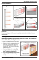
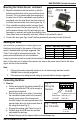
ENFORCER Curtain Sensors Sample Installations: Typical Door/Window Frame Windows Indoor Fence Tops Garages/Gates/Walls Skylights Important: Do not connect to power until the sensor is completely installed and the installation has been double-checked. Choosing a Location: When used outdoors, place the curtain sensor under a roof or shelter. This will reduce the chance of false alarms caused by rain or snow.
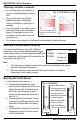
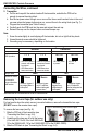
ENFORCER Curtain Sensors Choosing a Location, continued: Do not mount where the transmitter or Fig. 2: Orientation to Sun receiver could be splashed by water or mud. NO Do not mount where unit could be suddenly exposed to a bright light, OK* such as a floodlight or a passing car’s headlight. Do not let sunlight or any direct beam of TX RX light shine directly on the curtain beam *Only if unavoidable. Mount so transmitter, not receiver, faces RX sensor. If unavoidable, mount so the TX the sun.
ENFORCER Curtain Sensors Mounting the Curtain Sensor, continued: Fig. 5: Plastic cap 2. Mount the transmitter and the receiver so that the hiding screw End Screw surface-mounted wires do not come out from above Cap the units. This is to prevent water from entering via Cover the wire holes. If this is unavoidable, use silicone to completely cover the area where the wires come out the holes to prevent water from entering (see Fig. 4). Tamper Button 3.
ENFORCER Curtain Sensors Connecting the Wires, continued: 2. Transmitter: a. Pull the end cap with the red wire leads off the transmitter, and slide the PCB out far enough to expose the wiring block. b. Run the two power wires through one or more of the three round knockout holes in the end cap near where the tamper button wires run; connect them to the wiring block (see Fig. 7). c. Program the transmitter (see Table 2 below). d. Carefully push the PCB back into the case and reinsert the end cap. e.
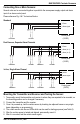
ENFORCER Curtain Sensors Connecting One or More Sensors: Several units can be connected together in parallel to the same power supply output and alarm input of an alarm control panel. Please reference Fig. 6 & 7 for terminal blocks. Standard } Power } Alarm signal Transmitter Control panel (12VDC) Receiver Dual Sensors, Separate Alarm Channels } Power } Alarm (ch. 1) } Alarm (ch.
ENFORCER Curtain Sensors Tamper Protection: The receiver and the transmitter both have a tamper switch on one end to protect against someone attempting to open the unit. However, there is no separate tamper output to the alarm control panel. Instead, the alarm output is triggered if the cover of the end cap with the tamper button is removed, if the transmitter or receiver is moved out of alignment, or if power is disconnected.