
User Manual

ENFORCER
®
Installation Manual
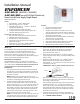
EAP-5D1Q (5A@12VDC, 2.5A@24VDC)
EAP-5D1MQ Same as EAP-5D1Q but PCB module only
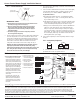
3. Run wires from the access control devices and accessories to the
power supply. The enclosure has knock-outs on the side, top,
bottom, and rear panels for running cables. Punch out the
appropriate knock-outs. See Fig. 1.
4. Set the desired DC output voltage (12 or 24 VDC) of the power
supply using the DIP switch. See Fig. 3. The default voltage output
setting is 12VDC.
5. Temporarily connect the AC power (110~240 VAC) to the "AC
INPUT" terminal block of the power supply by following the
terminal labels (i.e. "A" for active wire, "E" for ground wire and "N"
for neutral wire). See Fig. 3.
IMPORTANT: A clamp core must be installed on the power cord.
When AC power is connected, the green AC power indicator LED
and the red DC output indicator LED should be lit to indicate the
power supply is working properly.
Check the output voltage reading of the power supply's DC output
terminal block marked "- DC+" to make sure it is within the
normal range. See Fig. 3. The default output voltage of the power
supply should be about 12.6VDC at no load when set at 12VDC,
and about 25VDC at no load when set at 24VDC. After checking,
disconnect the AC input power.
6.
Connect the power input wires of the access control devices or
accessories to the power supply's DC output terminal block. See
Fig. 3. OBSERVE CORRECT POLARITY.
Access Control Power Supply, Single Output
What it is:
The ENFORCER Access Control Power Supply centralizes the power
sources for multiple 12 or 24 VDC-powered electronic locks or
accessories used in access control systems. The power input and
power output are enclosed in one heavy-duty, easy-to-install
enclosure. As a result, an ENFORCER Access Control Power Supply can
replace several separate individual power sources.
Note before installation:
The ENFORCER Power Supply is not waterproof or weatherproof.
Therefore, it must be mounted indoors where it will not be exposed to
rain or other moisture.
Installation must be done by qualified personnel,
and should conform to local and all other applicable codes.
Installation:
1. Find a good location for the enclosure. The enclosure should be
mounted where it is out of sight and protected from moisture and
the weather, but where an authorized person can have access for
servicing it in the future.
NOTE:
Make sure the space where the enclosure is to be
mounted has adequate ventilation. Otherwise, heat buildup inside
the enclosure could damage the electronic parts.
2. Locate the enclosure mounting holes. Using these holes as a
template, mark the location of the 4 screws on the wall with a
pencil. First screw in two
5
/
32
"
x 1" (4 x 26 mm) upper screws (not
included) until the gap between the wall and the screw head is
approximately 1/4" (6mm). Hang the enclosure on the two upper
screws using the enclosure's upper screw holes and adjust the
proper location of the enclosure. Screw in the two lower screws.
Then securely fasten the upper and lower screws.
NOTE:
For concrete walls, first drill four holes on the concrete wall
in the location of the screws. Then insert a "plastic anchor" (not
included) in each of the holes first before fastening the screws.
SPECIFICATIONS:
POWER:
!
Field selectable – 12VDC or 24VDC output.
!
Operating voltage input 110~240 VAC.
!
Adjustable voltage range (11~15 VDC, 23~28 VDC) to
compensate for voltage drop.
!
AC input fuse rating 3.15 Amps (glass fuse).
!
DC output overload sensing with red LED indicator and
automatic shutdown during short-circuit.
ENCLOSURE: (EAP-5D1Q model only)
!
Heavy-duty steel case to protect the power connections.
!
Removable steel cover for easy access.
!
Ventilation holes to prevent heat build-up.
!
Enough room for two 7AH batteries (not included).
!
Battery leads included.
!
Dimensions: 12
1
/
8
"x12
1
/
4
"x
3
9
/
16
"(308x311x90 mm).
!
Knock-out on the cover for optional cam lock.
Note: Products with model number that ends with "Q" or have a green “Q” sticker represents RoHS compliant products.
FEATURES:
!
AC power failure supervision relay.
!
Battery failure supervision relay.
!
Selectable 2.2K-Ohm End-of-Line (EOL) resistor for AC
failure and battery failure supervision relays via DIP switch.
!
Selectable delay timer (5 sec., 5 min., 5 hours) for AC failure
supervision relay via DIP switch.
!
Board designed with LED overload indicator and automatic
shutdown for short-circuit protection.
!
Over-current fuse-protected AC input.
!
Built-in back-up battery charger (Batteries not included).
!
Automatically switch to back-up battery if AC fails.
!
Individual AC input and DC output LED status indicators.
EAP-5D1Q Shown
Power cord
Clamp core