
User Manual


ENFORCER Passive Video Baluns
2 SECO-LARM U.S.A., Inc.
7
/
8
”
(22.5mm)
7
/
8
”
(22mm)
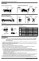
Overview:
Installation:
IMPORTANT: If using a balun to run power, make sure the terminals are connected to power at both ends. Connecting a
power supply to a camera’s data will cause damage to the camera. Double-check all connections
before powering units.
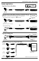
1. Video baluns are connected in pairs. Connect one balun to the CCTV camera’s BNC connector, and connect another to
the BNC connector of a DVR or other remote device.
2. Make sure the distance between the camera and the remote video device does not exceed 1,950ft (600m) for black and
white video or 1,300ft (400m) for color.
3. Run Cat 5e/6 cable (UTP) from the remote video device to the camera.
NOTE: Use T568-B wiring specification for RJ45 connections with EB-P501-22Q and EB-P501-23Q. See above.
4. Connect the Cat 5e/6 cable to both baluns. NOTE: Video baluns are polarity-sensitive.
a. Strip approximately
1
/
4
” (6mm) of insulation from the same two wires at both ends of a Cat 5e/6 cable.
b. Use a small screwdriver to loosen the video screw terminals on each balun. Insert one wire into each terminal at both
ends of the cable. After the wires have been inserted into the terminals, there should be no bare wire showing.
c. For models with power or data pass-through: Repeat steps 4a and 4b for the Power/Data terminals in order to run
either power or data through the balun.
NOTE: EB-P501-22Q and EB-P501-23Q are not compatible with any other baluns.
d. For EB-P501-22Q and EB-P501-23Q only: Connect the balun at one end to the camera’s DC jack. Connect the balun
at the other end to the power supply’s DC jack. Do not use these baluns with any other video/power/data balun.
5. Connect the video baluns into the BNC connector of the CCTV camera and the remote video device.
6. Test the connection by powering up the CCTV camera and remote video device to make sure they operate as expected.
EB-P501-01Q and EB-P501-01SQ
EB-P501-02Q and EB-P501-02SQ
Power/data screw
terminals
1
15
/
16
” (49.3mm)
7
/
8
”
(22.5mm)
EB-P501-20Q, EB-P501-20SQ
EB-P501-21Q, and EB-P501-21SQ
BNC connector
Video screw
terminals
1
1
/
4
”
(32mm)
9
/
16
”
(14.5mm)
BNC connector
Video screw
terminals
9
/
16
”
(14.5mm)
9
/
16
”
(15mm)
1
15
/
16
” (49.3mm)
Front
BNC
connector
EB-P501-22Q and EB-P501-23Q (Use T568-B Wiring Standard for RJ45)
BNC
connector
DC Plug
EB-P501-22Q: Red
EB-P501-23Q: Black
2
1
/
2
” (63mm)
2
13
/
16
” (71.3mm)
1
9
/
16
” (39.7mm)
Pair
Wire
Pin
EB-P501-22Q
EB-P501-23Q
1
Blue/White
5
Power –
Power –
Blue
4
Power +
Power +
2
Orange/White
1
Power –
Data +
Orange
2
Power +
Data –
3
Green/White
3
Power –
Power –
Green
6
Power +
Power +
4
Brown/White
7
Video +
Video +
Brown
8
Video –
Video –
T568-B Wiring Specification
Data terminals
(EB-P501-23Q only)
Top
RJ45
Use T568-B
Standard Only
3
/
4
” (19mm)
Rear
EB-P501-23Q shown.
Power/data screw
terminals
9
/
16
”
(14.5mm)
Front
Rear
BNC
connector
EB-P501-20Q shown.
Rear
Video screw
terminals
EB-P501-20Q and EB-P501-20SQ
EB-P501-21Q and EB-P501-21SQ
9
/
16
”
(15mm)
9
/
16
”
(14.5mm)
Rear
Video screw
terminals