Operator's Manual LIGHTNING® 2 Laser Detector
Thank you for purchasing an Apache Technologies, Inc. product. Your LIGHTNING® 2 Laser Detector is a premium quality tool that has been designed and manufactured to provide years of precise and reliable performance. This manual is an important part of your purchase as it will familiarize you with the unit and explain the numerous features that have been designed into it. Please read this manual thoroughly before using your detector.
Contents LIGHTNING® 2 Laser Detector General Description . ............................................................... 2 Operation . ............................................................................... 3 Special Functions .................................................................... 5 LCD ......................................................................................... 6 General Purpose Clamp .......................................................... 8 Maintenance and Safety .
General Description The LIGHTNING 2 high performance laser detector is designed to receive reference elevation information from rotating laser levels. The detector is designed to receive invisible laser beams as well as visible red beams. The detector includes a Liquid Crystal Display (LCD) on the front and rear for easy visual indication of detector status and grade information. Bright, multi-color LED's on the front provide additional visual indication of grade reference.
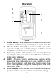
Operation 4 3 5 2 6 1 7 1. 2. 3. 4. 5. Front Power Switch - Turns the detector On and Off. Press to turn on. Press and hold for approximately 1 second to turn off. Volume Switch - Selects the volume level. Pressing switch cycles Loud, Off, and Low. Initial setting is Loud. When sound is Off, 1 beep indicates laser is detected. Accuracy Switch - Selects detection accuracy. Pressing switch cycles 3 accuracy options – Fine, Medium, and Coarse. Initial setting is Medium.
Operation 11 8 9 5 10 12 Back Reception Window - Houses the photocells which detect the laser signal. Window must be directed toward laser. 7. Beeper Output - Fast audible signal is detector Too High; solid is On-grade; slow is Too Low. 8. Tab Slot - accepts clamp tab and locks clamp in place. 9. Offset Notch - Used for transferring reference marks. Top of detector is 2" (50 mm) above On-grade. 10. Clamp Slots - Accepts clip-on general purpose clamp. 11. Serial Number / ID Label 12.
Operation - Special Functions Zero Deadband – Super fine accuracy (0.1mm) used when calibrating lasers. + With the power Off, press the Power and Accuracy switches at the same time to enter the zero deadband. The accuracy symbol with no bars will be displayed confirming zero deadband. Press the accuracy switch or cycle power to return to the standard accuracies. Line Alert – Special application to signal when the detector moves off on-grade.
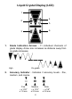
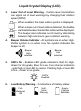
Liquid Crystal Display (LCD) 1 4 2 5 6 3 1. Grade Indication Arrows - 11 individual channels of grade display. Arrow size increases as distance away from on-grade increases. High 2. On-grade Low Accuracy Indicator - Indicates 3 accuracy levels - fine, medium, and coarse. Fine ~ ± 1/32" ± 1.0 mm Medium ~ ± 1/16" ± 2.0 mm 6 Wide ~ ± 1/8" ± 3.
Liquid Crystal Display (LCD) 3. Laser Out of Level Warning - Certain laser transmitters can signal out of level warnings by changing their rotation speed (RPM). When enabled, the laser outline symbol is displayed. When a laser out of level state is detected, the bubble vial inside the laser transmitter outline will be displayed. The beeper also indicates out of level by alternating between high and low to give a distinct warning. 4. Beeper Volume Indicator - All symbols are on when High.
General Purpose Clamp 2 3 1 4 5 1. Dovetail slots - attaches clamp to the back of detector. 2. Clamp lock tab and thumb release - tab for securing and thumb release for removing clamp from detector. 3. Reference Bar - Top of bar is aligned with detector On-grade location and marking notches. 4. Clamping Screw - tightens and loosens the clamp onto rods and staffs by moving the traveling jaw. 5. Bubble Vial Holes - pre-drilled holes for optional bubble vial kit screws.
General Purpose Clamp 2 1 1. Dovetail slots - attaches clamp to the back of detector. 2. Traveling jaw - grips tightly to rods and staffs and has a reversible face to adapt to various rods. Rectangular Rods Oval / Round Rods The slanted face grips tightly to round and oval rods. The flat face grips tightly to rectangular rods. To change the face of the jaw, remove the screw with a flathead screwdriver, flip the face over, and secure the screw back into the face.
Maintenance and Safety Detector Cleaning: Do not wipe dust or dirt off the detector reception or display windows with a dry cloth or other abrasive material as scratching could occur, reducing visibility through these windows. A soft cloth and mild soap and water are effective. The unit may be submerged under water or sprayed with a low pressure hose if necessary. Do not use any other fluids other than water or glass cleaner, as they may attack polymer components.
Specifications Working Radius: Beam Reception Range: Beam Window Height: Detectable Spectrum: Beam Sizes Received: Detection Accuracy: Zero: Fine: Medium: Wide: Display Channels: Beeper Volumes: Power Supply: Battery Life (alkaline): Operating Temperature: Storage Temperature: Automatic Shut-off: Weight (with batteries): Dimensions (HxWxD): Up to 1500 ft. (450m) Laser Dependent ± 45° 2" (50 mm) 610nm to 900nm 1/8" to 3/4" (4 mm to 19 mm) ± 0.
Warranty Apache Technologies, Inc. LIGHTNING 2 laser detectors and detector accessories are warranted to be free of defects in material and workmanship for a period of two years. This warranty period is twenty-four months from the date the product is delivered from the dealer to the purchaser or is put into service by a dealer as a demonstration unit or rental unit. In addition to the basic warranty above, Apache Technologies, Inc.
CE DECLARATION OF CONFORMITY Application of Council Directive: 89/336/EEC Manufacturer's Name: Apache Technologies, Inc. Manufacturer's Address: 8261 State Route 235 Dayton, OH 45424 USA European Representative Address: Apache Technologies Europe GmbH Langenberger Str.
8261 State Route 235 Dayton, OH 45424 USA Phone: (937) 482-0200 Fax: (937) 482-0030 www.apache-laser.