QLF210 INSTRUCTION MANUAL We’ll Make It Stress-Free If you have any questions along the way, just give us a call. 1-800-359-5520.
IMPORTANT SAFETY INSTRUCTIONS – SAVE THESE INSTRUCTIONS – PLEASE READ ENTIRE MANUAL PRIOR TO USE Before getting started, let’s make sure this mount is perfect for you! 1 Does your TV weigh more than 110 lbs. (49.8 kg) including accessories? 2 What is your wall made of? No — Perfect! 110 lbs. Yes — This mount is NOT compatible. Visit secura-av.com or call 1-800-359-5520 (UK: 0800-056-2853) to find a compatible mount. (49.
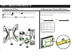
Dimensions in. [mm] 3-D TV INTERFACE 610mm 24.02in 400mm 15.75in 265mm 10.43in WALL PLATE SIDE VIEW - EXTENDED TOP VIEW - EXTENDED 5deg 9mm .35in 80mm 3.15in 145mm 5.71in 200mm 7.87in 15deg 25deg 25deg ESTIMATED 55" TV INTERFACE - OPTION 2 200mm 7.87in 200mm 7.87in TOP VIEW - RETRACTED 269.5mm 10.61in SIDE VIEW - RETRACTED NOTE: TV shifts 7.28 in. (18.5 cm) to the right or left when in the home position. Consider this when selecting the location of your wall mount. 100mm 3.94in 185mm 7.
Supplied Parts and Hardware WARNING: This product contains small items that could be a choking hazard if swallowed. Before starting assembly, verify all parts are included and undamaged. If any parts are missing or damaged, do not return the damaged item to your dealer; contact Customer Service. Never use damaged parts! NOTE: Not all hardware included will be used.
STEP 2 Parts and Hardware Adjustments Lag Bolt Washers Hex Keys .695 x .350 x.075 in. 14 x3 Lag Bolts 5/16 x 2¾ in.
STEP 1 Attach TV Bracket to TV 1.1 Prepare the TV Plate 1.2 Measure Your TV Hole (VESA) Pattern Separate TV bracket 01 from wall plate 03 using hex key 17 . 02 by removing the two screws NOTE: Save the screws 03 and wall plate Measure the width and height of your TV hole (VESA) pattern in mm. Record your measurements: 02 for later installation. mm x Height Width 02 75 mm 100 mm 200 mm 300 mm 400 mm 600 mm = 7.5 cm = 10 cm = 20 cm = 30 cm = 40 cm = 60 cm ≈ ≈ ≈ ≈ ≈ ≈ mm 3 in. 4 in. 7 7/8 in.
1.3 Assemble Your TV Bracket Dimensions in mm 04 TV Hole (VESA) Pattern (in mm) Determine which TV bracket configuration to use, A or B based on your TV hole (VESA) pattern measurements. A Dimensions in mm B 200 300 x 400 400 x 400 600 x 400 200 06 06 01 TV Hole (VESA) Pattern (in mm) 18 100 100 x 100 200 x 200 04 200 01 05 100 200 04 06 These smaller hole patterns only use TV plate 01 . Do not use TV brackets 04 and 05 , and four screws 06 .
1.4 Screw Diameter 1.5 Determine Spacers and Screw Length Hand thread screws into the threaded inserts on the back of your TV to determine which screw diameter (M6, or M8) to use. a: Use no spacers for: b: Spacers supplied for: Flat back TVs (AND TV closer to the wall). a ƕ Round (irregular) back TVs ƕ Extra space needed (for cables or inset mounting holes) b Standard configurations are shown.
1.6 Attach TV Bracket to TV * * For TV Hole (VESA) Patterns Position TV plate 01 over your TV hole pattern and secure using your selection: (a) screw/washer or (b) screw/washer/spacer. 100 x 100 200 x 200 CAUTION: Avoid potential personal injuries and property damage! DO NOT use power tools for this step. Tighten the screws only enough to secure the TV bracket to the TV. DO NOT overtighten the screws.
1.6 Attach TV Bracket to TV * * For TV Hole Slide TV brackets 05 onto the ends of the TV bracket assembly (TV plate 01 and TV bracket 04 ) as shown. (VESA) Patterns 300 x 400 400 x 400 600 x 400 Center all pieces horizontally and vertically over your TV hole pattern and secure together using four screws 06 using hex key 18 . Secure the entire assembly to your TV using your selection: (a) screw/washer or (b) screw/washer/spacer.
STEP 2A Attach Wall Plate Wood Stud Installation CAUTION: Avoid potential personal injuries and property damage! ƕ ƕ ƕ Drywall covering the wall must not exceed 5/8 in. (16 mm) Minimum wood stud size: common 2 x 4 in. (51 x 102 mm) nominal 1½ x 3½ in. (38 x 89 mm) Stud center must be verified 1. 2. Locate your stud. Verify and mark the center of the stud by finding the stud edges using an awl, a thin nail, or an edge to edge stud finder.
3. Drill the two pilot holes using a 7/32 in. (5.5 mm) diameter drill bit. IMPORTANT: Pilot holes must be drilled to a depth of 2 ¾ in. (70 mm). Be sure you mark and drill into the center of the stud. Install wall plate assembly 02 using two lag bolts 15 and two washers 14 Tighten lag bolts 15 only until the washers 14 are pulled firmly against the wall plate assembly 02 . 4.
STEP 2B Attach Wall Plate Solid Concrete or Concrete Block Installation CAUTION: Avoid potential personal injuries and property damage! ƕ ƕ ƕ Mount the wall plate assembly 02 directly onto the concrete surface Minimum solid concrete thickness: 8 in. (203 mm) Minimum concrete block size: 8 x 8 x 16 in. (203 x 203 x 406 mm) 1. 2. Position the wall plate 02 on the wall at your desired height. Level the wall plate 02 and mark the hole locations. Drill three pilot holes using a 3/8 in.
3. Insert three anchors 16 . CAUTION: Be sure the anchors are seated flush with the concrete surface. Install wall plate 02 using three lag bolts 15 and three washers 14 . Tighten the lag bolts only until the washers are pulled firmly against the wall plate. 4. CAUTION: Avoid potential personal injury or property damage! All lag bolts MUST BE firmly tightened to prevent unwanted movement of the wall plate 02 . Ensure the wall plate is securely fastened to the wall before continuing on to the next step.
STEP 3 Attach TV to Wall Plate HEAVY! You may need assistance with this step. 1. Hang the TV bracket 01 onto the wall plate assembly 02 . 2. Allow the TV and bracket assembly to rest against the wall plate assembly 02 . 1 TV bracket configuration A shown. 01 2 TV bracket configuration A shown.
3. Secure the TV bracket 01 to the wall plate assembly 02 with locking screws 03 that you removed in STEP 1.1 on PAGE 6. CAUTION: Avoid potential personal injury or property damage! locking screws 03 must be tightened to secure the TV to the wall plate assembly 02 . 3 15 01 02 17 TV bracket configuration A shown.
TV Adjustments TILT ADJUSTMENT LEVEL ADJUSTMENT REMOVING THE TV To adjust the tilt level of your TV, loosen the tilt adjustment screws on both sides of the arm assembly, adjust the TV to the desired tilt angle and retighten the tilt adjustment screws. NOTE: Once your TV is in place, tighten the tilt adjustment screws to prevent unwanted movement. To adjust the leveling of your TV, loosen the bottom lag bolt 15 , level your TV, then tighten the bottom lag bolt 15 .
Thank you for choosing Secura! Please take a moment to let us know how we did: Email us: info@secura-av.com Call us: 1-800-359-5520 UK: 0800 056 2853 Milestone AV Technologies and its affiliated corporations and subsidiaries (collectively, “Milestone”), intend to make this manual accurate and complete. However, Milestone makes no claim that the information contained herein covers all details, conditions, or variations.
Milestone AV Technologies Australia Pty Ltd ACN 163 436 039 6/96 Gardens Drive, Willawong QLD 4110, Australia 07 32761355 Addendum -Australian Consumer Law -Warranty against defects Milestone AV Technologies Australia Pty Ltd warrants its Milestone/Secura products to be free of defects in material and workmanship for the product's Warranty Period . The Warranty Period commences on the original purchase date of the product.