Security Products SSG 500-series Hardware Installation and Configuration Guide Juniper Networks, Inc. 1194 North Mathilda Avenue Sunnyvale, CA 94089 USA 408-745-2000 www.juniper.
Copyright Notice Copyright © 2009 Juniper Networks, Inc. All rights reserved. Juniper Networks, the Juniper Networks logo, JUNOS, NetScreen, ScreenOS, and Steel-Belted Radius are registered trademarks of Juniper Networks, Inc. in the United States and other countries. JUNOSe is a trademark of Juniper Networks, Inc. All other trademarks, service marks, registered trademarks, or registered service marks are the property of their respective owners. All specifications are subject to change without notice.
Table of Contents About This Guide 5 Organization .................................................................................................... 5 Conventions..................................................................................................... 6 Web User Interface Conventions .............................................................. 6 Command Line Interface Conventions ......................................................6 Requesting Technical Support ..........................
SSG 500-series Installation and Configuration Guide Default Device Settings .................................................................................. 33 Basic Device Configuration ............................................................................ 33 Admin Name and Password .................................................................... 34 Administrative Access ............................................................................. 34 Interface IP Address ......................
About This Guide The Juniper Networks Secure Services Gateway (SSG) 500-series devices are integrated router and firewall platforms. They provide Internet Protocol Security (IPSec) virtual private network (VPN) and firewall services for enterprise-edge environments. Juniper Networks offers two models of SSG 500-series devices: NOTE: SSG 520 SSG 550 The configuration instructions and examples in this document are based on the functionality of a device running ScreenOS 6.0.0.
SSG 500-series Installation and Configuration Guide Conventions This guide uses the conventions described in the following sections: “Web User Interface Conventions” on page 6 “Command Line Interface Conventions” on page 6 Web User Interface Conventions The Web user interface (WebUI) contains a navigational path and configuration settings. To enter configuration settings, begin by clicking a menu item in the navigation tree on the left side of the screen.
About This Guide NOTE: When entering a keyword, you only have to type enough letters to identify the word uniquely. For example, typing set adm u ang j12fmt54 is enough to enter the command set admin user angel j12fmt54. Although you can use this shortcut when entering commands, all the commands documented here are presented in their entirety. Requesting Technical Support Technical product support is available through the Juniper Networks Technical Assistance Center (JTAC).
SSG 500-series Installation and Configuration Guide Opening a Case with JTAC You can open a case with JTAC on the Web or by telephone. Use the Case Manager tool in the CSC at http://www.juniper.net/customers/cm/. Call 1-888-314-JTAC (1-888-314-5822—toll free in USA, Canada, and Mexico). For international or direct-dial options in countries without toll-free numbers, visit us at http://www.juniper.net/customers/support/requesting-support/.
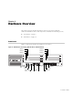
Chapter 1 Hardware Overview This chapter provides detailed descriptions of the Secure Services Gateway (SSG) 520 and SSG 550 device and components. It includes the following sections: “Front Panel” on page 9 “Back Panel” on page 14 Front Panel Figure 1 shows the front panel of an SSG 500-series device.
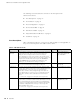
SSG 500-series Installation and Configuration Guide The following sections describe the elements on the front panel of an SSG 500-series device: “Port Descriptions” on page 10 “Power Button” on page 11 “Reset Config Button” on page 11 “Device Status LEDs” on page 11 “Ethernet Port LEDs” on page 12 “Physical Interface Module Slots” on page 13 “USB Ports” on page 13 Port Descriptions Table 1 describes the function, connector type, and speed/protocol (if applicable) of the ports on
Hardware Overview Power Button The power button is located on the left side of the front panel. You use the power button to power the device on and off. When you power on the device, ScreenOS starts as the power supply completes its startup sequence. See “Powering the Device On and Off” on page 26 for more information. Reset Config Button The Reset Config button restarts the device.
SSG 500-series Installation and Configuration Guide Table 2: Device Status LED Descriptions (Continued) Name Color Status Description ALARM Red On steadily Critical alarm: Failure of hardware component or software module Firewall attacks detected Amber On steadily Major alarm: Low memory (less than 10% remaining) High CPU utilization (more than 90% in use) Session full Maximum number of VPN tunnels reached HA status changed or redundant group member not found HA Off No alarms
Hardware Overview Physical Interface Module Slots Physical interface modules (PIMs) let you add Ethernet and WAN interfaces to your SSG 500-series device. To install and remove PIMs, see “Replacing a PIM” on page 46. For more information about installing and configuring PIMs, see the PIM and Mini-PIM Installation and Configuration Guide. CAUTION: PIMs are not hot-swappable. Always switch off the device before inserting or removing PIMs.
SSG 500-series Installation and Configuration Guide To transfer data between a USB storage device and an SSG 500-series device: 1. Connect the USB storage device to either the upper or lower USB port on the security device. 2. Save the files from the USB storage device to the internal flash storage on the device with the save {software | config | image-key} from usb filename to flash command. 3. Stop the USB port with the exec usb-device stop command before removing the USB storage device.
Hardware Overview For PSU servicing instructions, see “Replacing Power Components (SSG 550 Only)” on page 48. NOTE: Do not mix SSG 550 PSU types. The only supported combinations are AC+AC and DC+DC. The POWER LED on the front panel of an SSG 500-series device glows either green or red. Green indicates correct function and red indicates PSU failure. Table 6 describes the LED states on the field-installable AC and DC PSUs.
SSG 500-series Installation and Configuration Guide Figure 6: SSG 550 Device Replaceable AC PSU Faceplate Ejector tab Input power light Power cord receptacle Handle DC Power Supply Unit The fixed DC PSU faceplate for an SSG 520 device contains an ejector tab, an input power light, and two DC power terminal blocks that connect to power cables.
Hardware Overview To ground the device before connecting power, connect a grounding cable to earth ground and then attach the cable to the lug on the rear of the chassis. For more information, see “Chassis Grounding” on page 22.
SSG 500-series Installation and Configuration Guide 18 Back Panel
Chapter 2 Installing and Connecting the Device This chapter describes how to install an SSG 500-series device in a standard 19-inch equipment rack and how to connect cables and power to the device.
SSG 500-series Installation and Configuration Guide Before You Begin The location of the chassis, the layout of the equipment rack, and the security of your wiring room are crucial for proper device operation. CAUTION: To prevent abuse and intrusion by unauthorized personnel, install the device in a secure environment.
Installing and Connecting the Device There are two ways to rack-mount an SSG 500-series device: Center-mount—attach the left and right mounting brackets to the middle of each side of the chassis. Front-mount—attach the left and right mounting brackets to the front of each side of the chassis. To install an SSG 500-series device into a rack: 1. Have one person grasp the sides of the device, lift the device, and position it in the rack. 2.
SSG 500-series Installation and Configuration Guide Organizing Interface Cables Arrange network cables as follows to prevent them from dislodging or developing stress points: Secure cables so that they are not supporting their own weight as they hang to the floor. Place excess cable out of the way in neatly coiled loops. Use fasteners to maintain the shape of cable loops.
Installing and Connecting the Device 3. Use a grounding cable to connect the device to earth ground, and do the following: a. Verify that a licensed electrician has attached an appropriate grounding-cable lug to the grounding cable. b. Connect one end of the grounding cable to a proper earth ground, such as the rack in which the device is installed. c. Connect the other end of the grounding cable to the two-hole grounding lug at the rear of an SSG 500-series device.
SSG 500-series Installation and Configuration Guide CAUTION: There is no standard color coding for DC power cables. The color coding used by the external DC power source at your site determines the color coding for the leads on the power cables that attach to the terminal studs on each power supply. You must ensure that power connections maintain the proper polarity. The power source cables might be labeled (+) and (–) to indicate their polarity.
Installing and Connecting the Device Figure 11: Connecting DC Power-Cable Lugs DC terminal block Lug -48V RTN Washer Grounding lugs Screw with captive washer d. Secure the positive (+) DC source power-cable lug to the RTN terminal. e. Secure the negative (–) DC source power-cable lug to the –48 VDC terminal. f. Dress the power cables appropriately. CAUTION: Ensure that the DC cables do not touch the two screws on the chassis that are adjacent to the terminal block.
SSG 500-series Installation and Configuration Guide Powering the Device On and Off To power on the device, press the power button. ScreenOS starts as the power supply completes its startup sequence. The POWER LED illuminates during startup and remains on steadily when the device is operating normally. NOTE: The PSU in the rear panel of the device may include a power switch. If such a switch is included, make sure the switch is in the ON position.
Installing and Connecting the Device Figure 12: Basic Cabling Example T1 T1 Untrust Network PORT 0 PORT 1 PORT 0 STATUS STATUS T1 PORT 1 PORT 0 STATUS AL WER AR M STATUS 0 TX/RX SLOT NUMBER US AT ST HA POWER RESET CONFIG TX/RX 0/0 LINK TX/RX 0/1 LINK TX/RX 0/2 LINK 10/100/1000 TX/RX Console STATUS 10/100/1000 LINK 0 PO PORT 1 STATUS GB SFP 0/3 LINK CONSOLE AUX Internal Switch Trusted LAN PORT 1 STATUS T1 STATUS PORT 0 USB 1 2 3 4 5 6 SSG 550M DMZ Switch DMZ
SSG 500-series Installation and Configuration Guide 28 Connecting the Device to a Network
Chapter 3 Configuring the Device ScreenOS software is preinstalled on SSG 500-series devices. When the device is started, it is ready to be configured. While the device has a default factory configuration that lets you initially connect to the device, you must perform further configuration for your specific network requirements.
SSG 500-series Installation and Configuration Guide Accessing the Device You can configure and manage an SSG 500-series device in several ways: Console—The Console port on the device lets you access the device through a serial cable connected to your workstation or terminal. To configure the device, you enter ScreenOS command line interface (CLI) commands on your terminal or in a terminal-emulation program on your workstation. For more information, see “Using a Console Connection” on page 30.
Configuring the Device 3. Plug the other end of the RJ-45 CAT5 cable into the Console port on the SSG 500-series device. Figure 13 shows the arrangement of the cable and adapter. Figure 13: Establishing a Console Connection Serial port on workstation DB-9 adapter CAT5 RJ-45 cable Console port on SSG 500-series device BER NUM SLOT 0 1 PORT 0 PORT W PO ER US AT ST HA POWER 1 E CONSOL RESET CONFIG 10/100 AUX 1 2 3 E E 4 5 6 E E USB /1000 g003510 M AR AL STATUS STATUS 4.
SSG 500-series Installation and Configuration Guide Using the WebUI To use the WebUI, the workstation from which you are managing the device must initially be on the same subnetwork as the device. To access the device with the WebUI: 1. Connect your workstation to the port labeled 0/0 (ethernet0/0 interface), which is prebound to the Trust security zone. 2. Ensure that your workstation is configured with a static IP address in the 192.168.1.0/24 subnet. 3.
Configuring the Device Default Device Settings Table 7 describes the default interface-to-zone bindings on an SSG 500-series device. Table 7: Default Interface-to-Zone Bindings Port Label Interface Zone 0/0 ethernet0/0 (default IP address is 192.168.1.1/24) Trust 0/1 ethernet0/1 DMZ 0/2 ethernet0/2 Untrust 0/3 ethernet0/3 HA Note that the ethernet0/0 interface has the default IP address 192.168.1.1/24 and is configured for management services.
SSG 500-series Installation and Configuration Guide Admin Name and Password The administrative user has complete privileges to configure a device. We recommend that you change the default admin name (netscreen) and password (netscreen) immediately.
Configuring the Device CLI set interface ethernet0/0 ip ip_addr/mask save Management Services ScreenOS provides services for configuring and managing a device, such as SNMP, SSL, and SSH, which you can enable on a per-interface basis. You cannot configure WAN interfaces for management services.
SSG 500-series Installation and Configuration Guide Domain Name System Server The Domain Name System (DNS) server on the network maintains a database for resolving hostnames and IP addresses. Devices access the configured DNS servers to resolve hostnames. In ScreenOS, you configure the IP addresses for the primary and secondary DNS servers and the time of the day at which the device performs a DNS refresh.
Configuring the Device WebUI Network > Routing > Destination > New (trust-vr): Enter the following, then click OK: Network Address/Netmask: 0.0.0.0/0.0.0.0 Gateway: (select) Interface: ethernet0/2 (select) Gateway IP Address: ip_addr CLI set route 0.0.0.0/0 interface ethernet0/2 gateway ip_addr save High Availability Configuration An HA port lets you cable two devices together and configure them to work as a redundant group. A redundant group consists of one primary device and one backup device.
SSG 500-series Installation and Configuration Guide Figure 14: HA Cabling Connections Untrust Zone R1 R2 Switch F Switch C T1 PORT 1 PORT 0 T1 STATUS 10/100/1000 10/100/1000 LINK PO M AR 1 2 POWER RESET CONFIG TX/RX 0/0 LINK TX/RX 0/1 LINK TX/RX 0/2 LINK 10/100/1000 TX/RX 0/3 LINK CONSOLE AUX USB 1 2 3 4 5 6 SSG 550 SSG 550 WER STATUS 10/100/1000 10/100/1000 LINK PO M AR 1 2 SLOT NUMBER POWER AL RESET CONFIG TX/RX 0/0 LINK TX/RX 0/1 LINK TX/RX 0/2 LINK 10/10
Configuring the Device Primary Unit 2. Connect a crossover cable from ethernet0/0 to Switch A. 3. Connect a crossover cable from ethernet0/1 to Switch B. 4. Connect a crossover cable from ethernet0/2 to Switch C. Backup Unit 5. Connect a crossover cable from ethernet0/0 to Switch D. 6. Connect a crossover cable from ethernet0/1 to Switch E. 7. Connect a crossover cable from ethernet0/2 to Switch F. Switches 8. Cable together Switch A and Switch D. 9. Cable together Switch B and Switch E. 10.
SSG 500-series Installation and Configuration Guide PIM Configuration To configure the interfaces on physical interface modules (PIMs), refer to the PIM and Mini-PIM Installation and Configuration Guide. Basic Firewall Protections The devices are configured with a default policy that permits workstations in the Trust zone of your network to access any resource in the Untrust security zone, while outside computers are not allowed to access or start sessions with your workstations.
Configuring the Device Restarting the Device You may need to restart the device in order to implement new features, such as when you change between route and transparent mode or when you add new license keys. The following sections describe two methods of restarting the device: “Restarting the Device with the CLI Reset Command” on page 41 “Restarting the Device with the WebUI” on page 41 Restarting the Device with the CLI Reset Command To restart the device with the CLI reset command: 1.
SSG 500-series Installation and Configuration Guide 4. Click Reset. An alert box prompts you to confirm that you want to reset the device. 5. Click OK. The device resets. Also, an alert box prompts you to leave your browser open for a few minutes and then log back into the device. Resetting the Device to Factory Defaults If you lose the admin password, or you need to clear the configuration of your device, you can reset the device to its factory default settings.
Configuring the Device 4. Press the y key. The following message appears: !! Reconfirm Lost Password Reset !! If you continue, the entire configuration of the device will be erased. In addition, a permanent counter will be incremented to signify that this device has been reset. This is your last chance to cancel this command. If you proceed, the device will return to factory default configuration, which is: device IP: 192.168.1.1; username: netscreen, password: netscreen.
SSG 500-series Installation and Configuration Guide 44 Resetting the Device to Factory Defaults
Chapter 4 Servicing the Device This chapter describes service and maintenance procedures for SSG 500-series devices. It includes the following sections: NOTE: “Required Tools and Parts” on page 45 “Replacing a PIM” on page 46 “Replacing Power Components (SSG 550 Only)” on page 48 “Upgrading Memory” on page 52 “Replacing the Air Filter” on page 54 For safety warnings and instructions, refer to the Juniper Networks Security Products Safety Guide.
SSG 500-series Installation and Configuration Guide Replacing a PIM Both SSG 500-series devices have six slots in the front panel for Ethernet or WAN physical interface modules (PIMs). PIMs are field installable and replaceable. CAUTION: Power off the device before removing or installing PIMs. PIMs are not hot-swappable. Removing a Blank Faceplate To maintain proper airflow through the device, blank faceplates should remain over slots that do not contain PIMs.
Servicing the Device Removing a PIM To remove a PIM: 1. Place an electrostatic bag or antistatic mat on a flat, stable surface to receive the PIM. 2. Attach an ESD grounding strap to your bare wrist, and connect the strap to the ESD point on the device. 3. If the device is powered on, press and release the power button to power off the device. Verify that the POWER LED is off. 4. Label the cables connected to the PIM so that you can later reconnect each cable to the correct PIM. 5.
SSG 500-series Installation and Configuration Guide 3. Grasp the handles on each side of the PIM faceplate. On some PIMs the handles are metal ears attached to the PIM faceplate. Other PIMs have long screws that serve as the handles. 4. Align the edges of the PIM circuit board with the guide rails at each side of the PIM slot. 5. Slide the PIM in until it seats firmly in the device. CAUTION: Slide the PIM straight into the slot to avoid damaging the components on the PIM. 6.
Servicing the Device CAUTION: Do not leave a power supply slot empty while the device is operational. The power supply or a blank power-supply faceplate must remain in the chassis for proper airflow. Removing a Power Supply Unit To remove an AC power-supply unit (PSU) from a device: 1. Attach an ESD grounding strap to your bare wrist, and connect the strap to the ESD point on the device. 2. Unplug the power cord from the power-source receptacle. 3.
SSG 500-series Installation and Configuration Guide 2. Loosen the retaining screws on the terminal block. 3. Remove the feed wires. CAUTION: Ensure that the DC cables do not touch the two screws on the chassis that are adjacent to the terminal block. Contact between the DC cables and the chassis screws will cause a circuit failure. 4. With your thumb, slide the ejector tab on the power-supply faceplate to the right, and hold it in place to unlock the power supply. 5.
Servicing the Device WARNING: Before installing a DC power supply, you must shut off current to the DC feed wires that lead to the power supply. 2. Using both hands, slide the PSU into the chassis until you feel resistance. 3. Firmly push the power supply into the chassis until it comes to a stop. Make sure that the PSU is flush with any other adjacent PSU. 4. Attach the feed wires to the terminal block.
SSG 500-series Installation and Configuration Guide Upgrading Memory You can upgrade a device that has a single 256 MB single in-line memory module (SIMM) dynamic random access memory (DRAM) module to two 512 MB modules (1GB of memory). NOTE: The device must have 1GB of memory installed to run ScreenOS content security features: Web filtering Antivirus Antispam Intrusion protection system (deep inspection) To upgrade the memory on an SSG 500-series device: 1.
Servicing the Device Figure 18: Memory Module Slots Back Panel Slots 1 and 2 Slots 3 and 4 Front Panel NOTE: Install 512 MB memory modules either in slots 1 and 3 or in slots 2 and 4. Do not install memory modules in adjacent slots. 6. Release the 256 MB SIMM DRAM module by pressing your thumbs downward on the locking tabs on each side of the module so that the tabs swivel away from the module (Figure 19). Figure 19: Removing a Memory Module 7. Grip the long edge of the memory module and slide it out.
SSG 500-series Installation and Configuration Guide Figure 20: Installing a Memory Module 9. Locate the appropriate slot for the second 512 MB SIMM DRAM module. Repeat step 8 to install the second memory module in the slot. 10. To replace the top panel on the chassis, set the front edge of the top panel into the groove that runs along the top front edge of the chassis. Then lower the top panel onto the chassis. 11.
Servicing the Device To remove an air filter: 1. Remove the filter cover by squeezing the plastic tabs on each side of the filter cover. Figure 21: Air Filter Components Air filter PORT W PO AL ER AR M TU STA 0 Filter cover STATUS S HA R POWE T RESE IG CONF Plastic tab Plastic tab 2. Pull the filter cover away from the chassis. 3. Remove the old filter. 4. Place the new filter in the opening. 5.
SSG 500-series Installation and Configuration Guide 56 Replacing the Air Filter
Appendix A Specifications This appendix provides general system specifications for an SSG 500-series device. It includes the following sections: “Physical” on page 57 “Electrical” on page 58 “Environmental Tolerance” on page 58 “Certifications” on page 59 “RoHS and WEEE” on page 59 “Connectors” on page 60 Physical Table 8 provides the physical specifications for SSG 500-series devices. Table 8: SSG 500-series Physical Specifications Description Value Chassis dimensions 3.44 in.
SSG 500-series Installation and Configuration Guide Electrical Table 9 provides the electrical specifications for an SSG 500-series device.
Specifications Certifications Table 11 provides the device certifications for the SSG 500-series device. Table 11: SSG 500-series Device Certifications Certification Type Certification Name NEBS GR-63-CORE Issue 2, GR-1089-CORE Issue 3 Safety CAN/CSA-C22.2 No.
SSG 500-series Installation and Configuration Guide Connectors Figure 23 shows the pin numbering of the RJ-45 connectors for the Console and AUX ports. Figure 23: RJ-45 Connector Pin Numbering 1 8 Table 12 lists the pinouts of the RJ-45 connectors for the Console and AUX ports.
Specifications Table 13 lists the pinouts for the DB-9 adapter. Table 13: DB-9 Adapter Pinouts DB-9 Pin RJ-45 Pin Name I/O Description 1 N/C DCD <– Carrier Detect 2 3 RxD <– Receive Data 3 6 TxD –> Transmit Data 4 7 DTR –> Data Terminal Ready 5 4 Ground – Signal Ground 6 2 DSR <– Data Set Ready 7 8 RTS –> Request To Send 8 1 CTS <– Clear To Send 9 N/C RING <– Ring Indicator Table 14 lists the RJ-45 connector pinouts for the Gigabit Ethernet ports.
SSG 500-series Installation and Configuration Guide 62 Connectors
Index A AC grounding .................................................................23 AC power supply ......................................................15, 16 installing ...................................................................50 replacing cord ..........................................................51 admin name and password ..........................................34 administrative access ....................................................34 ALARM LED .................................
SSG 500-series Installation and Configuration Guide R rack mount ..................................................................... 21 resetting to factory default ........................................... 42 restarting the device...................................................... 41 S SFP transceivers ............................................................ 13 shutting down a device ................................................. 26 STATUS LED ...............................................