
Specifications

SSG 500-series Installation and Configuration Guide
60 Connectors
Connectors
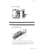
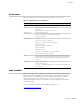
Figure 23 shows the pin numbering of the RJ-45 connectors for the Console and
AUX ports.
Figure 23: RJ-45 Connector Pin Numbering
Table 12 lists the pinouts of the RJ-45 connectors for the Console and AUX ports.
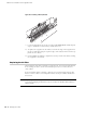
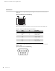
Figure 24 shows the pin numbering of the connector on the DB-9 adapter supplied
with the device.
Figure 24: DB-9 Connector Pin Numbering
Table 12: Console and AUX RJ-45 Connector Pinouts
Pin Name I/O Description
1RTS OutO Request To Send
2 DTR Out O Data Terminal Ready
3TxD O Transmit Data
4GND - Chassis Ground
5GND - Chassis Ground
6 RxD I Receive Data
7DSR I Data Set Ready
8 CTS I Clear To Send
18