Secure Computing SG User Manual Secure Computing 4810 Harwood Road San Jose, CA 95124-5206 Email: support@au.securecomputing.com Web: www.securecomputing.com Revision 3.1.
Contents 1. Introduction...............................................................................................1 SG Gateway Appliances (SG3xx, SG5xx Series).................................................. 1 SG Rack Mount Appliances (SG7xx Series) ......................................................... 4 SG PCI Appliances (SG6xx Series)....................................................................... 7 Document Conventions ...................................................................
DHCP Server ..................................................................................................... 111 Web Cache ........................................................................................................ 115 QoS Traffic Shaping .......................................................................................... 123 IPv6.................................................................................................................... 125 SIP ...............................
6. USB ........................................................................................................240 USB Mass Storage Devices .............................................................................. 240 USB Printers ...................................................................................................... 247 Printer Troubleshooting ..................................................................................... 253 USB Network Devices and Modems........................
1. Introduction This manual describes the features and capabilities of your SG unit, and provides you with instructions on how to best take advantage of them. This includes setting up network connections (in the chapter entitled Network Connections), tailoring the firewall to your network (Firewall), and establishing a virtual private network (Virtual Private Networking). It also guides you through setting up the SG unit on your existing or new network using the web management console (Getting Started).
The SG565, SG560, SG570, SG575 and SG580 may also connect to a DMZ (demilitarized zone) network. A DMZ is a separate local network typically used to host servers accessible to the outside world. It is separated both physically and by the firewall, in order to shield your LAN from external traffic. The SG unit allows you to establish a virtual private network (VPN). A VPN enables remote workers or branch offices to connect securely to your LAN over the public Internet.
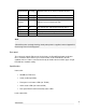
WAN Activity Flashing Network traffic on the Internet network interface WLAN Flashing Network traffic on the Wireless network interface DMZ Activity Flashing Network traffic on the DMZ network interface Serial Activity Flashing For either of the SG unit COM ports, these LEDs indicate receive and transmit data HA On The SG unit has switched to a backup device Online On An Internet connection has been established VPN On Virtual private networking is enabled Online On An Internet connect
• 10/100BaseT LAN port (SG530, SG550) • 10/100BaseT 4 port LAN switch (SG300) • 10/100BaseT DMZ port (SG570, SG575) • 10/100BaseT 4 port VLAN-capable switch (SG560, SG565, SG580) • Rear panel Ethernet link and activity status LEDs Enviromental • External power adaptor (voltage/current depends on individual model) • Front panel operating status LEDs: Power, Heart Beat • Operating temperature between 0° C and 40° C • Storage temperature between -20° C and 70° C • Humidity between 0 to 95% (
Label Activity Description Power On Power is supplied to the SG unit H/B (Heart Beat) Flashing The SG unit is operating correctly On If this LED is on and not flashing, an operating error has occurred.
Specifications Internet link • Two 10/100baseT Ethernet ports (C, D) • Two GbE ports (E, F – SG710+ only) • Serial port • Online status LEDs (Online, Failover) • Ethernet link and activity status LEDs LAN/DMZ link • Two 10/100BaseT 4 port LAN switches • Ethernet link and activity status LEDs Enviromental • Front panel operating status LEDs: Power, H/B • Operating temperature between 0° C and 40° C • Storage temperature between -20° C and 70° C • Humidity between 0 to 95% (non-condensing
SG PCI Appliances (SG6xx Series) Note The SG PCI appliance range includes models SG630 and SG635. The SG PCI appliance is a hardware based firewall and VPN server embedded in a 10/100 Ethernet PCI network interface card (NIC). It is installed into the host PC like a regular NIC, providing a transparent firewall to shield the host PC from malicious Internet traffic, and VPN services to allow secure remote access to the host PC.
The other is the host PC's IP address, which is configurable through the host operating system, identically to a regular NIC. This is the IP address that other PCs on the LAN see. It should be dynamically (DHCP) or statically configured to use the same gateway, DNS, etc. settings as a regular PC on the LAN. Note It is possible to configure the SG PCI appliance to run in masquerading mode. This is discussed in the chapter entitled Firewall.
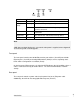
Location Activity Description Top right (Power) On Power is supplied to the SG unit (top right). Bottom right (Heart beat) Flashing The SG unit is operating correctly (bottom right). Top left Flashing Data is being transmitted or received (top left). On The SG unit is attached to the network (Network activity) Bottom left (Network link) Note If Heart beat does not begin flashing shortly after power is supplied, refer to Appendix D, Recovering From a Failed Upgrade.
Document Conventions This document uses different fonts and typefaces to show specific actions. Warning/Note Text like this highlights important issues. Bold text in procedures indicates text that you type, or the name of a screen object (e.g. a menu or button).
2. Getting Started This chapter provides step-by-step instructions for installing your SG unit. These instructions are identical to those in the printed Quick Install Guide that shipped with your SG unit. Upon completing the steps in this chapter, your SG gateway or rack mount appliance is installed in a network configuration similar that depicted in the figure to the right.
SG Gateway Appliance Quick Setup Unpack the SG unit Check that the following items are included with your SG unit: Power adapter SG CD Network cable On the rear panel of the SG unit you will see network, serial and possibly USB ports, a Reset/Erase button, and a power inlet. The front panel of the SG unit contains activity LEDs (lights) that vary slightly between models. These provide information on the operating status of the SG unit.
LAN subnet mask: 255.255.255.0 The SG unit needs an IP address suitable for your LAN before it is connected. You may choose to use the SG unit’s initial network settings above as a basis for your LAN settings. Connect the supplied power adapter to the SG unit. If you are setting up the SG300, attach your PC’s network interface card directly to any network port on its LAN switch using the supplied network cable.
Note If there is more than one existing network connection, select the one corresponding to the network interface card to which the SG unit is attached. Select Internet Protocol (TCP/IP) and click Properties (or in 95/98/Me, TCP/IP -> your network card name if there are multiple entries) and click Properties. Select Use the following IP address and enter the following details: IP address: 192.168.0.100 Subnet mask: 255.255.255.0 Default gateway: 192.168.0.
Note If you wish to retain your existing IP settings for this network connection, click Advanced and Add the secondary IP address of 192.168.0.100, subnet mask 255.255.255.0. Set up the SG unit’s password and LAN connection settings Launch your web browser and navigate to 192.168.0.1. Select Quick Setup Wizard from the center of the page. A log in prompt is displayed.
Note The new password takes effect immediately. You are prompted to enter it when completing the next step. The quick setup wizard is displayed. Changing the Hostname is not typically necessary. Select how you would like to set up your LAN connection then click Next. Note You must select Manual configuration in order to enable the SG unit’s built-in DHCP server. The SG unit’s DHCP server automatically configures the network settings of PCs and other hosts on your LAN.
Select Skip: LAN already configured if you wish to use the SG unit’s initial network settings (IP address 192.168.0.1 and subnet mask 255.255.255.0) as a basis for your LAN settings, and you do not wish to use the SG unit’s built-in DHCP server. Skip to the next step. You may choose to Obtain LAN IP address from a DHCP server on LAN if you have an existing DHCP server, and wish to rely on it to automatically configure the SG unit’s LAN connection settings (not recommended). Skip to the next step.
Set up the SG unit’s Internet connection settings First, attach the SG unit to your modem device or Internet connection medium. If necessary, give the modem device some time to power up. Select your Internet connection type and click Next. The options displayed differ depending on the connection type selected. If you are connecting using a Cable Modem, select your ISP, or Generic Cable Modem Provider if yours does not appear.
Set up the SG unit’s switch Note This page will only display if you are setting up the SG560, SG565 or SG580. Otherwise skip to the next step. By default, the SG unit’s switch A behaves as a conventional switching hub. However, it may be configured so that each port behaves as if it were physically separate from the others. Select a configuration for the SG unit’s switch then click Next.
Connect the SG unit to your LAN Review your configuration changes. Once you are satisfied, click Finish to activate the new configuration. Note If you have changed the SG unit’s LAN connection settings, it may become uncontactable at this point. This step describes how to set up the PCs on your network to access the SG unit and the Internet. Connect the SG unit to your LAN if you haven’t already done so. If you are setting up the SG300, connect PCs and/or your LAN hub directly to its LAN switch.
If you do not want to use a DHCP server, proceed to Manual configuration of your LAN. Automatic configuration of your LAN By selecting Manual Configuration for the SG unit’s LAN connection, and supplying DHCP Server Address Range, the SG unit’s DHCP server is already set up and running. Each PC on your LAN must now be set up to automatically obtain network settings. Click Start -> (Settings ->) Control Panel and double click Network Connections (or in 95/98/Me, double click Network).
Quick setup is now complete. Automatic configuration of your LAN using an existing DHCP server If you chose to have the SG unit Obtain LAN IP address from a DHCP server on LAN, It is strongly recommended that you add a lease to your existing DHCP server to reserve the IP address you chose for the SG unit’s LAN connection. If you chose to set the SG unit’s LAN connection settings using Manual configuration, you may simply remove this address from the pool of available addresses.
IP address is an IP address that is part of the same subnet range as the SG unit’s LAN connection (if using the default settings, 192.168.0.2 – 192.168.0.254). Subnet mask is the subnet mask of the SG unit’s LAN connection (if using the default settings, 255.255.255.0). Default gateway is the IP address of the SG unit’s LAN connection (if using the default settings, 192.168.0.1). Preferred DNS server is the IP address of the SG unit’s LAN connection (if using the default settings, 192.168.0.
Note Power is ON when power is applied. H/B (heart beat) flashes when the SG unit is running. Each of the network ports has two LEDs indicating link, activity and speed. In its factory default state, the four status LEDs next to Power flash. If these LEDs do not behave in this manner before your SG unit is attached to the network, perform a factory reset. Press the black Erase button on front panel twice within two seconds to restore factory default settings.
Connect one of the ports of network switch A (A1 – A4) directly to your PC’s network interface card using the supplied network cable. Next, modify your PC’s network settings to enable it to communicate with the SG unit. Click Start -> (Settings ->) Control Panel and double click Network Connections (or in 95/98/Me, double click Network). Right click on Local Area Connection and select Properties.
Preferred DNS server: 192.168.0.1 Note If you wish to retain your existing IP settings for this network connection, click Advanced and Add the secondary IP address of 192.168.0.100, subnet mask 255.255.255.0. Set up the SG unit’s password and LAN connection settings Launch your web browser and navigate to 192.168.0.1. Select Quick Setup Wizard from the center of the page. A log in prompt is displayed.
Note The new password takes effect immediately. You are prompted to enter it when completing the next step. The quick setup wizard is displayed. Changing the Hostname is not typically necessary. Select how you would like to set up your LAN connection then click Next. Note: You must select Manual configuration in order to enable the SG unit’s built-in DHCP server. The SG unit’s DHCP server automatically configures the network settings of PCs and other hosts on your LAN.
You may choose to Obtain LAN IP address from a DHCP server on LAN if you have an existing DHCP server, and wish to rely on it to automatically configure the SG unit’s LAN connection settings (not recommended). Skip to the next step. If you selected Manual configuration, some additional information is required. Otherwise, skip to the next step. Enter an IP address and Subnet Mask for the SG unit’s LAN connection. Note Take note of this IP address and subnet mask, as you will need them later on.
Note If you have changed the SG unit’s LAN connection settings, it may become uncontactable at this point. This step describes how to set up the PCs on your network to access the SG unit and the Internet. Connect PCs and/or your LAN hub to switch A on the SG unit. Set up the PCs on your LAN Each PC on your LAN must now be assigned an appropriate IP address, and have the SG unit’s LAN IP address designated as its gateway and as its DNS server.
Select Internet Protocol (TCP/IP) and click Properties (or in 95/98/Me, TCP/IP -> [your network card name] if there are multiple entries) and click Properties (in 95/98/Me, you may also have to click the IP Address tab). Check Obtain an IP address automatically, check Obtain DNS server address automatically and click OK (in 95/98/Me, reboot the PC if prompted to do so).
Note The purpose of restarting the computers is to force them to update their automatically configured network settings. Alternatively you can use a utility such as ipconfig to release then renew the DHCP lease, or disable and re-enable the network connection. Manual configuration of your LAN Click Start -> (Settings ->) Control Panel and double click Network Connections (or in 95/98/Me, double click Network).
Note If you have changed the SG unit’s LAN connection settings, browse to the new LAN IP address. Select Network Setup from the Network Setup menu. In the row labeled Port C, select your Internet connection type from the Change Type drop down list. If you are connecting using a Cable Modem, select your ISP, or Generic Cable Modem Provider if yours does not appear.
SG PCI Appliance Quick Setup Unpack the SG unit Check that the SG CD is included with your appliance: On the SG unit is a single 10/100 network port, a Reset button and four LEDs (lights). The LEDs provide information on the operating status of your SG unit. The two LEDs closest to the network port indicate network link and network activity. The two LEDs furthest from the network port indicate Power and Heart Beat. The Heart Beat LED blinks when the SG unit is running.
Set up your PC to connect to the web management console Note The following steps assume you want to set up your SG unit in bridged mode, so that it sits between your PC and the LAN, transparently filtering network traffic. If you want to set up your SG unit for NAT mode or to connect directly to your ISP, refer to the User Manual on the SG CD (\doc\UserManual.pdf). The SG unit ships with initial network settings of: IP address: 192.168.0.1 Subnet mask: 255.255.255.
IP address: 192.168.0.100 Subnet mask: 255.255.255.0 Leave the Default gateway and DNS server addresses blank. Set up the SG unit’s password and network connection settings Launch your web browser and navigate to 192.168.0.1. Select Network Setup from the Networking menu. A log in prompt is displayed. Enter the initial user name and password for the SG unit: User name: root Password: default Note If you are unable to connect to the management console at 192.168.0.
In the row labeled Bridge, click the Modify icon. Note The purpose of this step is to configure the IP address for the web management console. For convenience, this is generally a free IP address on your LAN. If your LAN has a DHCP server running, you may set up the SG unit and your PC to obtain their network settings automatically. Proceed to Automatic configuration. Otherwise, you must manually specify network settings for both the SG unit and your PC. Proceed to Manual configuration.
Check DHCP assigned. Anything in the IP Address and Subnet Mask fields is ignored. Click Update. Click Start -> (Settings ->) Control Panel and double click Network Connections. Right click on Local Area Connection (or appropriate network connection for the newly installed PCI appliance) and select Properties. Select Internet Protocol (TCP/IP) and click Properties and click Properties. Check Obtain an IP address automatically, check Obtain DNS server address automatically and click OK.
Note Contact your network administrator if you are unsure of any of these settings. The first IP address is used by the web management console Enter this address as the IP Address, and the subnet mask for your LAN as the Subnet mask. Ensure DHCP assigned is unchecked. You may also enter one or more DNS Server(s) and a Gateway address to be used by the SG unit, not your PC, for access to the Internet. Typically this is not necessary, as only your PC needs to access the Internet. Click Update.
Select Internet Protocol (TCP/IP) and click Properties. Enter the following details: IP address is the second free IP addresses that is part of the subnet range of your LAN. Subnet mask is the subnet mask of your LAN. Default gateway is the IP address of your LAN’s default gateway. Preferred DNS server is the IP address of the DNS server used by PCs on your LAN. Click OK. Attach your SG unit’s Ethernet port to your LAN’s hub. Quick setup is now complete.
From a network security standpoint, it may be desirable to disable the Reset switch after initial setup has been performed. This is accomplished by removing the jumper linking CON2 on the SG unit. This jumper is labeled Remove Link to Disable Erase. The SG Management Console The various features of your SG unit are configured and monitored using the management console. Follow the steps from the beginning of this chapter to set up your PC to access the management console.
3. Network Setup This chapter describes the Network Setup sections of the web management console. Here you can configure each of your SG unit’s Ethernet, wireless and serial ports. It is accessed by clicking Network Setup under the Network Setup section of the main web management console menu. The QoS Traffic Shaping and IPv6 sections are also described towards the end of this chapter.
A network interface is configured by selecting a connection type from the Change Type pull down menu. The current configuration can be viewed or modified by clicking the Edit icon. Clicking the Delete icon unconfigures a network interface; you are prompted to confirm this action. Multifunction vs. Fixed-function Ports Some SG units have network ports with labels corresponding to the port’s function, i.e. LAN, DMZ and Internet/WAN. These are said to be fixed-function ports.
Note The switches’ ports can not be configured individually; a switch is configured with a single function only (e.g., LAN switch, DMZ switch). SG560, SG565 and SG580: Multifunction Ports The SG560, SG565 and SG580 have generically named Ethernet ports (ports A1, A2, A3, A4 and B). By default, switch A functions as a regular LAN switch, with network traffic passing freely between its ports. Typically, port B is used as your primary Internet connection.
Direct Connection A direct connection is a direct IP connection to a network, i.e. a connection that does not require a modem to be established. This is typically a LAN, DMZ or Guest connection, but may also be an Internet connection. Network settings may be assigned statically, or dynamically by a DHCP server. Note Direct connections may be added to a network bridge, this is discussed in Bridging later in this chapter. Network settings Click the Edit icon of the interface your wish to modify.
To have your SG unit obtain its LAN network settings from an active DHCP server on your local network, check DHCP assigned. Note that anything in the IP Address,Subnet Mask and Gateway fields are ignored. You may also enter one or more DNS servers. Multiple servers may be entered separated by commas. Firewall class The Firewall class setting controls the basic allow/deny policy for this interface.
If an Ethernet port is experiencing difficulties auto-negotiating with another device, Ethernet Speed and duplex may be set manually. On rare occasions it may be necessary to change the Ethernet hardware or MAC Address of your SG unit. The MAC address is a globally unique address and is specific to a single SG unit. It is set by the manufacturer and should not normally be changed.
For aliases on interfaces that have the DMZ or Internet firewall class, you must also setup appropriate Packet Filtering and/or Port forwarding rules to allow traffic on these ports to be passed onto the local network. See the chapter entitled Firewall for details. IPv6 Click the IPv6 tab to Enable IPv6 for this connection. Note To route and filter IPv6 traffic, you must also check the Enable IPv6 option on the IPv6 page; refer to the section entitled IPv6 towards the end of this chapter.
Select the connection method to use in establishing a connection to your ISP: PPPoE, PPTP, DHCP, or Manually Assign Settings. Note Use PPPoE if your ISP uses username and password authentication to access the Internet. Use PPTP if your ISP has instructed you to make a dial-up VPN connection to the Internet. Use DHCP if your ISP does not require a username and password, or your ISP instructed you to obtain an IP address dynamically.
PPPoE To configure a PPPoE or PPPoA connection, enter the user name and password provided by your ISP. You may also enter a descriptive Connection Name if you wish. Click Finish. Note For PPPoE/PPPoA connections, ensure your DSL modem is set to operate in bridged mode. Typically, for PPPoE connections, your DSL modem must be set to use LLC multiplexing/encapsulation. For PPPoA connections, your DSL modem must be set to use VC-based multiplexing/encapsulation.
The Local IP address is used to connect to the PPTP server and is not typically your real Internet IP address. You may also enter a descriptive Connection Name if you wish. Click Finish or Update. DHCP DHCP connections may require a Hostname to be specified, but otherwise all settings are assigned automatically by your ISP. You may also enter a descriptive Connection Name if you wish. Click Finish or Update.
The latter two settings are optional, but are generally required for normal operation. Multiple DNS addresses may be entered separated by commas. You may also enter a descriptive Connection Name if you wish. Click Finish or Update. Connection (dial on demand) You may choose to bring up a PPPoE/PPPoA DSL, dialout or ISDN connection only when PCs on the LAN, DMZ or Guest network (via a VPN tunnel) are trying to reach the Internet and disconnect again when the connection has been idle for a specified period.
Ethernet configuration See the section entitled Ethernet configuration under Direct Connection. Aliases See the section entitled Aliases under Direct Connection. Cable Modem To connect to the Internet using a cable Internet service, select Cable Modem from the Change Type pull down menu for the interface that connects to your cable modem. Cable Modem connections have the interface firewall class of Internet.
Ethernet configuration See the section entitled Ethernet configuration under Direct Connection. Aliases See the section entitled Aliases under Direct Connection. Dialout and ISDN To connect to the Internet using a regular dialup or ISDN service, select Dialout from the Change Type pull down menu for the interface that connects to your dialup modem or ISDN TA. Dialout and ISDN connections have the interface firewall class of Internet.
By default, Dialout/ISDN connections are treated as “always on” and is kept up continuously. Alternatively, you may choose to only bring the connection up when PCs on the LAN, DMZ or Guest network (via a VPN tunnel) are trying to reach the Internet. For instructions, refer to the section entitled Dial on Demand further on in this chapter. Port settings If necessary, you may set the SG unit’s serial port Baud rate and Flow Control. This is not generally necessary.
If you wish, you may enter a descriptive Connection Name. Enter a free IP Address for Dial-In Clients, this must be a free IP address from the network (typically the LAN) that the remote user is assigned while connected to the SG unit. If you have configured several network connections, select the one that you want to connect remote users to from the IP Address for Dial-In Server pull down menu. This is typically a LAN interface or alias.
• Unencrypted Authentication (PAP): This is plain text password authentication. When using this type of authentication, the client passwords are transmitted unencrypted. Select the Required Encryption Level, access is denied to remote users attempting to connect not using this encryption level. Using Strong Encryption (MPPE 128 Bit) is recommended. Select the Authentication Database. This allows you to indicate where the list of valid clients can be found.
Click Next to continue. Select Dial-up to private network as the connection type and click Next to continue.
Tick Use dialing rules to enable you to select a country code and area code. This feature is useful when using remote access in another area code or overseas. Click Next to continue. Select the option Only for myself to make the connection only available for you.
Enter a name for the connection and click Finish to complete the configuration. Check Add a shortcut to my desktop to add an icon for the remote connection to the desktop. To launch the new connection, double-click on the new icon on the desktop. The remote access login screen appears as in the next figure. If you did not create a desktop icon, click Start -> Settings -> Network and Dial-up Connections and select the appropriate connection.
The SG unit supports a wide range of configurations through which you can utilize multiple Internet connections, and even multiple SG units, to help ensure Internet availability in the event of service outage or heavy network load. The following Internet availability services are provided by the SG unit. They may be configured individually, or in combination.
Once the Internet connections have been configured, specify the conditions under which the Internet connections are established. Internet Failover Note If you have configured your SG560, SG565 or SG580’s switch as separate ports, and are establishing multiple PPPoE ADSL Internet connections using two or more of these ports, it is important that each port is connected to a remote device with a unique MAC address.
Edit connection parameters The first step of configuring failover is to set failover parameters for each connection. These parameters specify how to test whether a connection is up and functioning correctly. On the Network Setup page, click the Failover & H/A tab. A list of the connections that you have configured is displayed under the Connection Failover tab, alongside ticks and crosses.
• Custom (advanced users only) allows you to enter a custom console command to run to determine whether the connection is up. This is typically a script you have written and uploaded to the SG unit. • Always Up means no test is performed, and Internet failover is disabled for this connection. If you wish, you may fine tune the timeouts for the failover test, however the defaults are usually suitable.
Ping Interval is the time to wait in between sending each ping, Failed Pings is the number of missed ping replies before this connection attempt is deemed to have failed. Click Finish. Modify failover levels (primary, secondary, tertiary) The second and final step of configured Internet failover is associating Internet connections with and primary, secondary and optionally tertiary connection levels. Recall that a connection level is one or more connections.
First, configure the Primary connection level. If you have a single Internet connection only, setting it to Enabled or Required has the same effect. For failover to occur, you must then configure at least the secondary connection level. Click Finish. This returns you to the main Connection Failover page. You’ll notice that ticks and crosses are display alongside each connection, describing how they are configured for each connection level.
Note If you have configured your SG560, SG565 or SG580’s switch as separate ports, and are establishing multiple PPPoE ADSL Internet connections using two or more of these ports, it is important that each port is connected to a remote device with a unique MAC address. This is almost definitely the case if each of the Internet connections are through different ISPs, otherwise you may have to request this specifically from your ISP.
Check Load Balance for each connection to enable for load balancing. Click Finish. Note Load balancing settings are not specified for each failover level; load balancing occurs when any two or more load balancing connections are up. Limitations of load balancing Load balancing works by alternating outgoing traffic across Internet connections in a round robin manner. It does not bond both connections together to work as one link, e.g.
Load balancing is not performed for incoming traffic. This scenario can be addressed using other solutions such as round robin DNS to alternate incoming connections between the two links. High Availability Just as Internet failover keeps a redundant Internet connection on stand-by should the primary connection fail, high availability allows a second SG unit to provide network connectivity should the primary SG appliance fail.
Enabling high availability On each of the devices, select the Failover & H/A, then the High Availability tab. You may use either the supplied script, /bin/highavaild, to manage the shared address, or you may write your own script, possibly based on /bin/highavaild. Note /bin/highavaild is a Tcl script. The SG unit uses TinyTcl, which provides a fairly extensive subset of regular Tcl’s features. Documentation is available from: http://tinytcl.sourceforge.
Advanced configurations The supplied script is intended as a starting point for more advanced High Availability configurations. By default, a device is considered "up" and a candidate to become the master if it is powered up and connected to the network segment. If you wish to have the device become master only if some other service is available (say, an Internet connection), a Test command may be added that checks for the availability of that resource and returns 0 if it is available.
DMZ Network Note Not available on the SG300, SG530, SG550 or SG PCI appliances. A DMZ (de-militarized zone) is a physically separate LAN segment, typically used to host servers that are publically accessible from the Internet. Servers on this segment are isolated to provide better security for your LAN. If an attacker compromises a server on the LAN, then the attacker immediately has direct access to your LAN.
Configuring a Direct Connection is described in detail in the section entitled Direct Connection towards the beginning of this chapter. Services on the DMZ network Once you have configured the DMZ connection, configure the SG unit to allow access to services on the DMZ. There are two methods of allowing access. If the servers on the DMZ have public IP addresses, you need to add packet filtering rules to allow access to the services. See the section called Packet Filtering in the chapter entitled Firewall.
Not available on the SG300, SG530, SG550 or SG PCI appliances. The intended usage of Guest connections is for connecting to a Guest network, i.e. an untrusted LAN or wireless networks. Machines connected to the Guest network must establish a VPN connection to the SG unit in order to access the LAN, DMZ or Internet. By default, you can configure the SG’s DHCP server to hand out addresses on a Guest network, and the SG’s VPN servers (IPSec, PPTP, etc.
Configuring a Direct Connection is described in detail in the section entitled Direct Connection towards the beginning of this chapter.
Wireless Note SG565 only. The SG unit’s wireless interface may be configured as a wireless access point, accepting connections from 802.11b (11 Mbit/s) or 802.11g (54 Mbit/s) capable wireless clients. Typically, the SG unit’s wireless interface is configured in one of two ways; with strong wireless security (WPA) to bridge wireless clients directly onto your LAN, or with weak wireless security as a Guest connection.
Warning We strongly recommend that the wireless interface be configured as a LAN connection only if wireless clients are using WPA-PSK encryption/authentication. This is discussed in further detail later in this section. Configuring a Direct Connection is described in detail in the section entitled Direct Connection towards the beginning of this chapter. See the sections DMZ Network and Guest Network earlier in this chapter for further discussion of these network types.
ESSID: (Extended Service Set Identifier) The ESSID is a unique name that identifies a wireless network. This value is case sensitive, and may be up to 32 alphanumeric characters. Broadcast ESSID: Enables broadcasting of the ESSID. This makes this wireless network visible to clients that are scanning for wireless networks.
If Security Method is set to None, any client is allowed to connect, and there is no data encryption. Warning If you use this setting, then it is highly recommended that you configure wireless interface as a Guest connection, disable bridging between clients, and only allow VPN traffic over the wireless connection. WEP security method WEP (Wired Equivalent Privacy) allows for 64 or 128 bit encryption.
WEP Key Length: This sets the length of the WEP keys to be entered below. It is recommended to use 128 bit keys if possible. WEP Key: Enter up to 4 encryption keys. These must be either 10 hexadecimal digits (0 – 9, A – F) for 64 bit keys, or 26 hexadecimal digits for 128 bit keys. You must also select one of the 4 keys to be the default transmit key.
When the Access Control List is disabled (Disable Access Control List), any wireless client with the correct ESSID (and encryption key if applicable) can connect to the wireless network. For additional security, you can specify a list of MAC addresses (network hardware addresses) to either allow or deny.
Advanced To edit access control list settings, click the Edit icon alongside the Wireless network interface, click the Wireless Configuration tab, then the Advanced tab. Region: Select the region in which the access point is operating. This restricts the allowable frequencies and channels. If your region is not listed, select a region that has similar regulations. Protocol: • 802.11b only: Wireless clients can only connect using 802.11b (11 Mbit/s). Note that most wireless clients which support 802.
Preamble Type: The preamble is part of the physical wireless protocol. Using a short preamble can give higher throughput. However, some wireless clients may not support short preambles. Enable RTS: RTS (Request to Send) is used to negotiate when wireless clients can transmit. If you have two wireless clients that are out of range of each other, but both still within range of the access point, they may both attempt to transmit at the same time, causing a collision.
Connecting wireless clients The following steps detail how to configure your SG unit to bridge between its wireless and LAN interfaces. The result of this configuration would be similar to attaching a wireless access point in bridge mode to one of the SG unit’s LAN ports. Individual settings and fields are detailed earlier in the Wireless section. The wireless and wired LAN interfaces share a single IP address, in this example the wireless interface shares the existing IP address of the wired LAN interface.
Select Allow authentication for MACs in the Access Control List and click Apply. Add the MAC address of each wireless client you wish to allow to connect. Click Advanced. Ensure the Region has been set appropriately. You may also restrict the Protocol to 802.11b only or 802.11g only if you wish. Generally, the other settings should be left at their default values. Click Apply. Click the Connections tab.
Under the main table, select Bridge and click Add. Select your wired LAN connection from the Existing Interface Configuration pull down box. This is the address to share between the interfaces. Click Next.
Alongside the wireless interface, check Bridged and select LAN from the Firewall Class pull down menu. Click Finish. Note If your LAN interface was previously configured to obtain an IP address automatically from a DHCP server, the SG unit now uses the MAC address of the wireless device when obtaining an IP address. You may have to update your DHCP server accordingly. Configure each wireless client with the Channel, ESSID, WPA Key and WPA Encryption method.
Another advantage is that network traffic not usually routed by unbridged interface, such as broadcast packets, multicast packets, and any non-IP protocols such as IPv6, IPX or Appletalk pass over the bridge to their destination host. Bridging network interfaces involves creating, then associating existing network interfaces with a Bridge interface. Warning You must trust all devices that are directly connected to bridged interfaces.
If you wish to transfer the IP address settings of an existing network connection to the bridge interface, select it from the Existing Interface Configuration pull down menu. Click Next. Note As the SG unit automatically directs network traffic, hosts on either side do not need to specify this IP address as a gateway to the networks connected to the bridge.
You may want to Enable Spanning Tree Protocol if you have multiple bridges on your network. It allows the bridges to exchange information, helping elimate loops and find the optimal path for network traffic. Forwarding Delay is the time in seconds between when the bridge interface comes online and when it begins forwarding packets. This usually only occurs when the unit first boots, or the bridge configuration is modified.
A guide to bridging across an IPSec tunnel using GRE is provided in the section entitled GRE over IPSec in the Virtual Private Networking chapter. VLANs Note VLANs are not supported by the SG300. VLAN stands for virtual local area network. It is a method of creating multiple virtual network interfaces using a single physical network interface. Packets in a VLAN are simply Ethernet packets that have an extra 4 bytes immediately after the Ethernet header.
Note Additionally, switch A on the SG560, SG565 and SG580 (but not the SG710 or SG710+) supports port based VLANs. One benefit of this feature is that you are able to assign individual functions to each of the ports on the switch, e.g. you might decide to use port A2 to connect to a DMZ, and port A3 as a second Internet connection. See the section entitled Port Based VLANs later in this chapter for details.
Removing VLANs To remove a VLAN, click the Delete icon alongside the VLAN interface in the main Network Setup -> Connections table. Port Based VLANs Note SG560, SG565 and SG580 only. The SG560, SG565 and SG580 have a VLAN-capable switch built in. This gives you the flexibility to either use it as a simple switch that allows access between all ports (this is the default), or use port based VLANs to control access between each individual port in the switch.
Typically, a tagged VLAN interface is used when you want to join an existing VLAN on the network, and an untagged VLAN interface is used when you are using the port based VLAN feature to isolate the ports so that you can configure each of them individually. Limitations of port based VLANs There are few further limitations to keep in mind when using port based VLANs: • The total bandwidth from the switch into the CPU is 100Mbits/s, which is shared between the 4 ports.
The following settings pertain to port based VLANs: • Enable port based VLANs: Check to enable port based VLANs. • Default port based VLAN ID: As the default VLAN is always untagged, typically you only need to change this from the default setting of 2 if you want another port to participate on an existing tagged VLAN with the ID of 2.
The following settings are displayed: • Interface: The port based VLAN capable interface on which to add the VLAN. • VLAN ID: If you are adding a VLAN interface to participate on an existing VLAN, enter its ID number here. Otherwise enter the next available VLAN ID; if the Default port based VLAN ID has been left at its default setting of 2, Port A2 uses VLAN ID 3, Port A3 uses VLAN ID 4, and so on. Note Some Cisco equipment uses tagged VLAN 1 for its own purposes.
Refer to the section entitled Tagged and untagged VLANs earlier in this chapter for further discussion of these settings. Click Update. This VLAN interface now appears in the Connections table, and you may configure it as you would any other network interface. Editing port based VLANs Once a VLAN has been added, you may edit the settings you entered in Adding port based VLANs by clicking its Edit icon in the main Network Setup -> Connections table.
Ensure Enable is checked and enter a descriptive GRE Tunnel Name for this tunnel. Enter the address of the remote GRE endpoint in Remote Address, e.g. the Internet IP address of a remote SG unit. Enter the address of the local GRE endpoint in Local Address. This is typically a free address on your main LAN. If your LAN connection has an alias address, it may also be a free address on the alias network.
6. Modify the firewall. In this example we use a dummy alias network of 10.254.0.0 / 255.255.0.0 to bridge two example local networks, one at Brisbane and one at Slough. These steps must be repeated for either end of the tunnel. Note that the two locations are using the same subnet. SG unit in Brisbane Internet address: 203.23.45.6 LAN address: 192.168.1.1 LAN alias: 10.254.0.1 LAN: 192.168.1.0 / 24 SG unit in Slough Internet address: 195.45.67.8 LAN address: 192.168.1.2 LAN alias: 10.254.0.
Create an IPSec tunnel between Brisbane and Slough. Select IPSec from the VPN section of the main menu and click New. For a complete overview of all available options when setting up an IPSec tunnel, refer to the IPSec section earlier in this chapter. Take note of the following important settings: Set the local party as a single network behind this appliance. Set the remote party as single network behind a gateway. For the Slough end’s Phase 2 Settings, specify the Local Network as 10.254.0.1 / 255.255.255.
At the Brisbane end, click Packet Filtering, the Custom Firewall Rules tab and add this custom firewall rule: iptables -I OUTPUT ! -o ipsec+ -d 10.254.0.1 -j DROP Click Update. GRE troubleshooting • Symptom: Cannot ping a host on the other side of the GRE tunnel. Ensure that there is a route set up on the GRE tunnel to the remote network. Ensure that there is a route on the remote GRE endpoint to the network at this end of the GRE tunnel. Check that there is a GRE interface created on the device.
Route management Note Route management does not have full GUI configuration support. We recommend that only advanced users familiar with the Zebra routing daemon and/or the RIP, BGP or OSPF routing protocol attempt configuration of this feature. Advanced users may configure the SG unit to automatically manage its routing tables, exchanging routes with other routers using RIP, BGP or OSPF protocol. Check Enable route management, select the desired Protocol and click Update.
password zebra!password In these examples,! denotes a descriptive comment, and # indicates a configuration line that is currently commented out, that you may want to uncomment depending on your network setup. In zebra.
#network eth2 ! Define neighbor routers to exchange RIP with if disabling multicast above in zebra.conf, or neighbors don't have multicast enabled #neighbor 192.168.45.238 #neighbor 192.168.45.231 ! Redistribute routing information for interfaces with RIP disabled redistribute connected ! Redistribute routing information from static route entries redistribute static ! Redistribute routing information from kernel route entries e.g. IPSec redistribute kernel Note RIP version 2 is used by default.
OSPF Note This example is adapted from the LARTC (Linux Advanced Routing & Traffic Control) dynamic routing howto, available from: http://lartc.org/howto/ LARTC is an invaluable resource for those wanting to learn about and take advantage the advanced routing capabilities of Linux systems. OSPF stands for Open Shortest Path First, and some of its principal features are: • Networks are grouped by areas, which are interconnected by a backbone area which will be designated as area 0.
The SG is configured to exchange routes with the routers named Atlantis, Legolas and Frodo. Ensure you have enabled OSPF under Route Management, then open zebra.conf and ospfd.conf for editing as described in the Route management section. In zebra.
! Uncomment and set telnet/vty passwords to enable telnet access on port 2604 #password changeme #enable password changeme ! Instruct ospfd about our network topology router ospf network 192.168.0.0/24 area 0 network 172.17.0.0/16 area 1 Restart route management to enable the updated configuration – uncheck Enable route management, click Update, check Enable route management and click Update.
Note The AS numbers used in this example are reserved, please get your own AS from RIPE if you set up official peerings. Ensure you have enabled BGP under Route Management, then open zebra.conf and bgpd.conf for editing as described in the Route management section. In zebra.conf, enter: hostname sg ! Uncomment and set telnet/vty passwords to enable telnet access on port 2602 #password changeme #enable password changeme In bgpd.
access-list local_nets deny any ! Our AS number router bgp 1 ! Our IP address bgp router-id 192.168.0.1 ! Announce our own network to other neighbors network 192.168.0.0/24 ! Advertise all connected routes (directly attached interfaces) redistribute connected ! Advertise kernel routes (manually inserted routes, IPSec) redistribute kernel ! Every 'router bgp' block contains a list of neighbors to which the router is connected: neighbor 192.168.1.1 remote-as 2 neighbor 192.168.1.
Workgroup/domain Note SG565 only. The Workgroup/Domain is the Windows workgroup or domain with which to share printers or network shares. These shared resources are not visible to machines on the LAN that are not members of this workgroup or domain. Administrative contact You may enter the email address of the local administrator of the SG unit for use as the SNMP sysContact field.
Check Enable DNS proxy to enable this feature. If you are using the SG unit’s DHCP server, you may also check Update DNS with local DHCP leases. This allows the SG unit’s DNS proxy to look up the names of devices that have requested IP address addresses. Dynamic DNS A dynamic DNS service is useful when you don’t have a static Internet IP address, but need to remain contactable by hosts on the Internet. Dynamic DNS service providers such as TZO.com and dyndns.
DHCP Server Note To configure your SG unit as a DHCP server, you must set a static IP address and netmask on the network interface on which you want the DHCP server to run; see the Direct Connection section of the chapter entitled Network Connections. To begin configuring the SG unit’s DHCP server, select DHCP Server from the Network Setup section of the web management console’s main menu.
• Enter the DNS Address to issue the DHCP clients. If this field is left blank, the SG unit's IP address is used. Leave this field blank for automatic DNS server assignment. If your SG unit is configured for DNS masquerading, you should either leave this field blank, or enter the IP address of the LAN port of the SG unit. • Optionally enter a Domain Name suffix to issue DHCP clients. • Optionally enter IP address of the WINS server to be distributed to DHCP clients in the WINS Address field.
There is an icon to Delete the address from the list of addresses to manage. You may also Free addresses that have been leased by hosts on your network, this causes the lease to expire immediately, leaving the address available for the next host that requests IP configuration.
Reserving IP addresses You may also reserve IP addresses for particular hosts, identifying them by hostname and MAC address. To reserve an IP address for a certain host, enter the following in the Add reserved IP address section. • Enter the Hostname of the DHCP client. • Enter the MAC address of the DHCP client. • Enter the reserved IP address for the DHCP client. Click Submit. DHCP status This main DHCP server page displays the status for each interface on which the DHCP server is running.
The Subnet is the network on which DHCP server is handing out addresses. Free Addresses displays the number of remaining available IP addresses that can be distributed. You may need to increase the number of IP addresses to hand out if this value is 0. DHCP Proxy The DHCP proxy allows the SG unit to forward DHCP requests from the LAN to an external server for resolution. This allows both static and dynamic addresses to be given out on the LAN just as running a DHCP server would.
A proxy-cache server implements Internet object caching. This is a way to store requested Internet objects (i.e., data available via HTTP, FTP, and other protocols) on a server closer to the user's network than on the remote site. Typically the proxy-cache server eliminates the need to re-download Internet objects over the available Internet connection when several users attempt to access the same web site simultaneously.
Local storage Note Network Storage and Local Storage cannot be used at the same time. Enabling one will automatically disable the other. Attach a USB storage device, click Storage then Local Storage. Enter a Cache size in MB. This is the maximum amount of space the web cache will utiize on the storage device. Note The size of this cache should be at least as big as the Cache size on the Main tab and not more than 90% of the total size of the storage area.
Note We recommend that you create a special user account to be used by the SG unit for reading and writing to the network share. If you have an existing account or wish to may the network share readable and writeable by everyone, you may skip the next step. To create an account, click Start -> Control Panel -> User Accounts -> Create a new account. Type a name for the new account, e.g. sguser, and click Next. Typically it is sufficient to grant this account Limited privileges.
Next, share the folder. Right click on the folder and select Sharing and Security. Select Share this folder and note the Share name, you may change this to something easier to remember if you wish. Finally, to set the security permissions of the newly created network share, click Permissions. If you wish to secure the network share with a username and password (recommended), click Add and type the user name the account to be used by the SG unit and click Check Names then OK.
Note The SG unit’s web cache uses port 3128 by default. Enter 3128 in Port, select Bypass proxy for local addresses and click OK. Peers The SG unit’s web cache can be configured to share cached objects with, and access objects cached by, other web caches. Web caches communicate using the Internet Cache Protocol (ICP). ICP is used to exchange hints about the existence of URLs in neighbour caches.
Check Enable ICAP functionality to enable the ICAP features of the SG unit's web cache. ICAP REQMOD server is the URL for an ICAP server's REQMOD service. This allows an ICAP server to modify web transaction requests, i.e. to process as they are being initially requested by the LAN PC, e.g. for URL filtering. It must begin with icap://, e.g.: icap://192.168.0.10:1344/reqmod ICAP RESPMOD server is the URL for an ICAP server's RESPMOD service. This allows an ICAP server to modify web transaction responses, i.
Objects larger than the Maximum cached object size in memory (KB) are NOT kept in the memory cache. This should be set high enough to keep objects accessed frequently in memory to improve performance whilst low enough to keep larger objects from hoarding cache memory. The Anonymity Level controls the amount of identifying information to be removed from web requests in order to protect your anonymity.
Select Packet Filtering from the Firewall menu, and click the Custom Firewall Rules tab. Add the following Custom Firewall Rules: iptables -t nat -D ContFilt -p tcp --dport 80 -j REDIRECT --to-port 81 iptables -t nat -A ContFilt -p tcp --dport 80 -j REDIRECT --to-port 3128 Click Update. Select Advanced from the System menu, click the Configuration Files tab. Click the Modify icon for squid.conf.
Click Enable and enter the Outbound Speed (upstream speed) of this interface’s network connection in megabits per second. Click Finish. Note If you have a PPTP or PPPoE connection to the Internet, enter approximately 80 – 90% of the speed that the ISP supplied to account for protocol overheads. ToS traffic shaping Traffic shaping provides a level of control over the relative performance of various types of IP traffic.
Check Enable Traffic Shaping, select a Default priority and click Submit to enable this feature. The Default priority is assigned to all network services other than those specifically added below. To add a service, click New then New again. Select the Protocol and Port on which this service runs. Select Priority for this service click Finish. IPv6 Check Enable IPv6 to enable IPv6 routing and packet filtering. Support for IPv6 is currently limited.
SIP (Session Initiation Protocol, RFC3261) is the protocol of choice for most VoIP (Voice over IP) phones to initiate communication. By itself, SIP does not work from behind masquerading firewalls, as the transfered data contains IP addresses and port numbers. Note If you use an external SIP service just as the Gizmo Project or Skype, you typically do not need to use the SIP proxy.
4. Firewall The SG unit is equipped with a fully featured, stateful firewall. The firewall allows you to control both incoming and outgoing access, so that PCs on local networks can have tailored Internet access facilities while being shielded from malicious attacks from external networks. The SG unit’s stateful firewall keeps track of outgoing connections (e.g. a PC on your LAN requesting content from a server on the Internet) and only allows corresponding incoming traffic (e.g.
Administration services The following figure shows the Administration Services page: By default the SG unit runs a web administration server, a Telnet and an SSH service. Access to these services can be restricted to specific interfaces. Typically, access to the web management console (Web/SSL Web) is restricted to hosts on your local network (LAN Interfaces).
You can also select to Accept echo request (incoming port) on Internet interfaces. The default is to disallow echo requests, so your SG unit does not respond to pings on its Internet interfaces. This may make it more difficult for external attackers scanning for hosts to discover your SG unit. Destination unreachable ICMP messages are always accepted. Web Server Click the Web Server tab to configure the SG unit’s administrative web server.
After changing the web server port number, you must include the new port number in the URL to access the pages. For example, if you change the web administration to port number 88, the URL to access the web administration is similar to: http://192.168.0.1:88 SSL/HTTPS (Secure HTTP) Note Not available on the SG300, SG530, SG570 or SG630. To enable SSL support on the SG unit, an RSA x509 certificate as well as its private key are required.
Upload SSL certificates If you have purchased or created SSL certificates for a web server, you can upload them to the SG unit under Upload SSL certificates tab. Click Browse to locate the Local Certificate (RSA x509 certificate) and its corresponding Private Key Certificate Create SSL certificates To create a self-signed certificate on the SG unit, click the Create SSL certificates tab.
A typical use of NAT rules is to forward packets destined for your Internet IP address to an internal web server or email server on your LAN. This is known as a port forward, or destination NAT as it alters the destination address of the packet. The first step in creating packet filter or NAT rules, is to define services (such as web or email) and addresses (such as your internal web server, or a trusted external host) under Definitions.
A service group can be used to group together similar services. For example, you can create a group of services that you wish to allow, and then use a single rule to allow them all at once. Select the services from the list of predefined services, or enter the port number to define a custom TCP, UDP, ICMP or IP service. A service may belong to multiple service groups. Addresses Addresses are a single IP address, or range of IP addresses, or a DNS hostname.
Adding or modifying an address is shown in the following figure: You may either add a Single Address or Range or DNS Hostname. You may also group previously added addresses together by defining an Address Group to simplify your firewall ruleset. Select how you would like to add the address or addresses, and click New. Either enter the DNS Hostname, the IP Address or address range and an optional descriptive Name, or select the addresses to group and enter a descriptive Name. Click Finish.
Packet Filtering Packet filter rules match traffic based on a combination of the source and destination address, incoming and outgoing interface, and destination service. Matched packets may be allowed or disallowed. Packet filter rules Click Packet Filter Rules. Click New to add a new filter rule. Any rules that have already been defined are displayed, you may Edit or Disable/Enable these rules by clicking the appropriate icon.
Note The first matching rule determines the action for the network traffic, so the order of the rules is important. You can use the Move Up and Move Down icons to change the order. The rules are evaluated top to bottom as displayed on screen. Adding or modifying a rule is shown in the following figure: The Action specifies what to do if the rule matches. • Accept means to allow the traffic. • Drop means to disallow the traffic.
• Input means filter packets destined for this unit. You can only select the incoming interface. • Output means filter packets generated by this unit. You can only select the outgoing interface. The Incoming Interface is the interface/network port that the SG unit received the network traffic on. Set this to None to match traffic destined for the SG unit itself. The Outgoing Interface is the interface/network port that the SG unit routes the network traffic out.
Rate limiting Note Rate Limit settings are only available when modifying rules. They cannot be specified when creating a new rule. Once you have created a packet filtering rule, you may specify rate limiting settings. These settings are useful for preventing a service from becoming unavailable should many connection attempts occur in a short period of time (e.g. in the case of a denial of service (DOS) attack). Packets that exceed the specified limit can be accepted, rejected or dropped, and can be logged.
• Reject: Disallow the rate limited packet, but also send an ICMP protocol unreachable message to the source IP address. • Drop: Silently disallow the rate limited packet. If Log if Limited is checked, then first packet of any rate limited connection will generate a log message. Log Prefix specifies the text to be placed at the start of the log message. This can be used to make it easier to identify which rules are being matched when inspecting the system log.
Source NAT rules are useful for masquerading one or more IP addresses behind a single other IP address. This is the type of NAT used by the SG unit to masquerade your private network behind its public IP address. To a server on the Internet, requests originating from the hosts behind masqueraded interface appear to originate from the SG unit, as matched packets have their source address altered.
Note The example shown in the screenshot above forwards the SSH (secure shell) protocol to an internal server (barry’s server). SSH allows encrypted remote access, typically to a server running Linux, BSD or another Unix-like operating system. In this example, port 2222 is used rather than the standard SSH port of 22, this is to allow remote access using SSH to the SG unit itself, which runs an SSH server on port 22.
This rule is applied to packets that match the critera described by the next four fields. Destination Address The destination address of the request, this is the address that is altered Protocol The protocol of the packet Ports The destination service port or ports of the request, note that many public ports may be forwarded to a single internal port The next two fields describe how matching packets should be altered.
Warning Precautions must be taken when configuring the mail server, otherwise you become susceptible to such abuse as unauthorized relaying of unsolicited email (spam) using your server. Configuration of the email server is outside the scope of this manual. Where possible, add packet filter rules to restrict access to the internal email server to trusted external hosts only. First, add a service group to group email services (SMTP, POP3 and IMAP). Click Definitions, the Service Groups tab, then New.
Enter smtp in Other TCP Ports. This is the protocol remote clients use for sending mail via the server. Click Finish. Click NAT, the Port Forwarding tab, then New. Click Advanced at the bottom of the page. Enter Mail server In Descriptive Name. Leave Enable and Create Packet Filter Rule checked. Leave Incoming Interface and Source Address as Any. Select your Internet connection in Destination Address. Click Predefined next to Services.
Select E-Mail from Services. Enter your internal email server’s IP address in To Destination Address. Click Finish. Configure mail clients on the Internet with the SG unit’s Internet IP address as the server to use for sending (SMTP) and receiving (POP3 or IMAP) mail. If your SG unit has a dynamic Internet IP address, consider using a dynamic DNS server; see Dynamic DNS in the DNS section of the chapter entitled Network Setup.
The following fields are displayed: Enable Uncheck to temporarily disable this rule Descriptive Name An arbitrary name for this rule This rule is applied to packets that match the critera described by the next four fields.
When adding a rule, you may either use Predefined addresses or services that have been added under Definitions, or click New to manually enter an address or service. 1-to-1 NAT This creates both a source NAT and destination NAT rule for mapping all services on an internal, private address to an external, public address. Note After adding a 1-to-1 NAT rule, you must manually create packet filter rules to allow incoming packets on the public address. Click Source NAT.
Descriptive Name An arbitrary name for this rule Enable Uncheck to temporarily disable this rule Private Address The private address to change Public Address The public address, typically a WAN interface alias Public Interface Select the interface on which the public address resides, this is typically Internet Note When adding a rule, you may either use Predefined addresses that have been added under Definitions, or click New to manually enter an address.
Note The displayed options apply to the firewall classes, not to the ports with these names. That is, the LAN interface options apply to all interfaces that are configured with a LAN connection type, not just to the port labelled as LAN. It strongly recommended that you leave Enable NAT from LAN/VPN interfaces to Internet interfaces checked. Typically, this is required to allow Internet access from the LAN.
The port forwarding rules set up via the UPnP Gateway are temporary. The list of configured UPnP port forwarding rules is cleared should the SG unit be power cycled, or should the internal or external interface become unavailable. The UPnP Gateway is intended for transitory application port forwarding, such as those established by some versions of Microsoft Messenger for file transfers.
Enter an arbitrary Description of service, the Name or IP address of the computer hosting this service on your network, the External Port number for this service and the Internal Port number for this service. Select whether the service uses the TCP or UDP protocol. Click OK. This rule now appears on the SG unit UPnP page, under Current UPnP Port Mappings. Connection Tracking Connection tracking keeps a record of what packets have passed through the unit, and how they relate to each other.
Note Implementations of protocols such as H.323 can vary, so if you are experiencing problems then you can try disabling the module. Check Enable Connection Logging to log connections to the system log as they are established and expire, however this may result in a lot of log messages if you have a large or busy network. Intrusion Detection Note The SG300, SG530, SG550, SG560, SG570 and SG630 provide Basic Instrusion Detection and Blocking only.
Read on to find out how using an IDS can benefit your network’s security, or skip ahead to the Basic or Advanced Intrusion Detection section for an explanation of configuration options. The benefits of using an IDS External attackers attempting to access desktops and servers on the private network from the Internet are the largest source of intrusions. Attackers exploiting known flaws in operating systems, networking software and applications, compromise many systems through the Internet.
IDB operates by offering a number of services to the outside world that are monitored for connection attempts. Remote machines attempting to connect to these services generate a system log entry providing details of the access attempt, and the access attempt is denied. Because network scans often occur before an attempt to compromise a host, you can also deny all access from hosts that have attempted to scan monitored ports.
Trigger count before blocking specifies the number of times a host is permitted to attempt to connect to a monitored service before being blocked. This option only takes effect when one of the previous blocking options is enabled. The trigger count value should be between 0 and 2 (o represents an immediate blocking of probing hosts). Larger settings mean more attempts are permitted before blocking and although allowing the attacker more latitude, these settings reduce the number of false positives.
Warning The list of network ports can be freely edited, however adding network ports used by services running on the SG unit (such as telnet) may compromise the security of the device and your network. It is strongly recommended that you use the pre-defined lists of network ports only. Advanced Intrusion Detection and Prevention (Snort and IPS) Advanced Intrusion Detection and Prevention is based on two variants of the tried and tested intrusion detection and prevention system Snort v2.
Check Enabled. Select the network Interface to monitor (Snort IDS only). This is typically Internet, or possibly DMZ. Check Use less memory to restrict Snort's memory usage (Snort IPS only). This results in slower signature detection throughput, but may be necessary if the device is configured to run many services, many VPN tunnels, or both Snort IDS and IPS. Rule sets are sets of defined patterns or rules used for the detection of attacks.
Log results to database to use a remote analysis server. If it is left unchecked, results are output to the device's system log (Advanced -> System Log). The device currently only supports the MySQL Database Type. Enter the table name of remote data in Database Name. Enter the IP address or resolvable Hostname of the analysis server. Enter the Database port of the analysis server. For MySQL type databases, this is typically 3306. Sensor Name is an arbitrary string that is prepended to the log output.
MySQL database http://www.mysql.com/downloads/mysql-4.0.html http://www.mysql.com/doc/en/index.html Apache web server http://httpd.apache.org/download.cgi http://httpd.apache.org/docs-2.0/ PHP scripting language for developing web pages http://www.php.net/downloads.php http://www.php.net/download-docs.php ADODB library to hide differences between databases used by PHP http://php.weblogs.com/adodb#downloads GD graphics library for GIF image creation used by PHP http://www.boutell.
Additionally, you can set up global block/allow lists for web sites that you always want to be accessible/inaccessible (Web Lists), or force users to have a personal firewall installed (ZoneAlarm) or ensure they are not running network services that may be exploited (Policy) before accessing the Internet. How access controls are applied Access control options operate in the following order for web access: 1. Web Lists allow 2. Web Lists deny 3. Security Policy enforcement 4. ACL allow 5. ACL block 6.
The Enable Access Control checkbox enables/disables the entire access control subsystem. This box must be checked for any access control operation to take place. The Default Action field defines the behaviour when none of the myriad of settings positively allow or block access. If changed to block by default, some definitions must be created elsewhere in access control to allow some network traffic or no access is possible.
Note To add or remove access controls user accounts, select Users from the main menu and click the Local Users tab. Access controls users should generally have only Internet Access (via. Access Controls) checked, with all other access permissions unchecked. See the Users section in the chapter entitled System for further details on adding user accounts. Users without web proxy access see a screen similar to the figure below when attempting to access external web content.
Browser setup The example given is for Microsoft Internet Explorer 6. Instructions for other browsers should be similar, refer to their user documentation for details on using a web proxy. From the Internet Options menu, select Tools. From the LAN Settings tab, select LAN Settings. Check Use a proxy server for your LAN… and Bypass proxy server for local address. All other options should remain unchecked. Click Advanced.
In the row labeled HTTP, enter your SG unit’s LAN IP address in the Proxy address to use column, and 81 in the Port column. Leave the other rows blank. In the Exceptions text box, enter your SG unit’s LAN IP address. Click OK, OK and OK again. ACL Access may be Blocked or Allowed by the Source (LAN) IP address or address range, the Destination (Internet) host’s IP address or address range, or the Destination Host’s name.
Web lists Access is be denied to any web address (URL) that contains text Added under URL Block List, e.g. entering xxx blocks access to any URL containing xxx, e.g.: http://www.xxx.com, http://xxx.example.com or www.test.com/xxx/index.html The Allow List also enables access to URLs containing the specified text. Note Defining large numbers of URL fragments to match against can result in a significant slowing down of WWW accesses.
In addition to enforcing the services aspect of security groups, it is possible to include a number of NASL (Nessus Attack Scripting Language) scripts in /etc/config on the unit and to define some or all of these to be run against the target hosts. Typically, one would use attack scripts from the Nessus suite to scan for specific vulnerabilities and exploits on a host. If any script detects such a vulnerability, Internet access is again blocked.
Content filtering allows you to limit the types of web based content accessed. Note Content filtering is not performed for addresses specified in Web Lists or ACL. Obtaining a content filtering licence Contact your local SG dealer to obtain a content filtering licence. When you purchase a content filtering licence, you are given a token to activate the licence. Navigate to http://www.cyberguard.
Content Check Enable Content Filtering enter your License key then continue on to set reporting options and which categories to block. Click Apply once these options have been set up to enable content filtering. Checking Enable Cache stores recently accessed pages’ ratings locally, to lower the response time the next time the page is accessed. It is recommended that you leave this checked. Blocked requests are submitted to the central content filtering server.
Select which categories you wish to block. Selecting Unratable blocks pages that the central content filtering database has not yet categorized. Webwasher Check Enable content filtering and paste in your Certificate and Private key. Check Allow accesses that cannot be rated to allow access to web sites that the Webwasher content filtering system has not yet rated. The default behaviour is to block all unrated sites. The SG unit dynamically retrieves rating categories from the Webwasher server.
Unchecking Allow access to newly defined categories restricts access to the categories you did not block when configuring content filtering. Leaving Allow access to newly defined categories checked allows access to any categories added after content filtering is configured. Check Identify users by account to send user names to the Webwasher reporting service. In order for this field to have any effect, Require User Authentication on the Main tab must be checked.
The Enable ZoneAlarm Pro support checkbox specifies if the ZoneAlarm Pro enforcement section of access control is active or not. Turning this feature on does involve a small sacrifice in the performance of this unit. The ZoneAlarm Hosts menu allows selection of the hosts which must be running ZoneAlarm Pro software to be able to access the Internet. The Check frequently checkbox indicates if local hosts should be queried as to their ZoneAlarm Pro status and version very often or less often.
Enable antivirus Select Antivirus from the Firewall section of the main menu. Check Enable. The Database mirror is the host from which the signature database is updated. Unless there is a specific host from which you want the SG unit to retrieve signature updates, leave this at the default setting of database.clamav.net. Select the frequency to Check for updates from the database mirror. The checks are quick and shouldn't cause a noticeable decrease to performance unless an update is necessary.
Storage It is recommended that you use a network or local share to provide storage for the virus database and temporary space for the scanning process. This greatly increases the effectiveness of the antivirus scanner. Network storage A network share is a shared folder or drive on a local Windows PC, or a PC running another operating system capable of SMB sharing (such as Mac OS X, or a Linux PC running the SAMBA service).
Launch Windows Explorer (Start -> (All) Programs -> Accessories -> Windows Explorer) and open up a folder or drive to dedicate as a network share for use by the SG unit’s web cache. Begin by disabling simple file sharing for this folder. From the Tools menu, select Folder Options. Click the View tab and under the Advanced settings section uncheck Use simple file sharing (Recommended). Click OK. Next, share the folder. Right click on the folder and select Sharing and Security.
Under the Storage -> Network Storage tab, check Use share. Enter the location of the network share in the format: \\HOSTNAME\sharename Enter the Username and Password for a user that can read and write to the network share. If you allowed Full Control to Everyone, you may leave these blank. Local storage Note SG565 only. Attach a USB storage device to one of the SG unit’s USB ports.
Under the Storage -> Local Storage tab, select the partition or device to use from the Device pull down menu, and click Submit. POP email The SG unit can scan email being sent by PCs on your LAN before delivering it to the destination mail server. Note Scanning of IMAP and web-based email is not supported. This service is configured differently depending on whether you want to scan all incoming email, or email being retrieved by specific PCs on your LAN only.
If most, but not all, of your internal email clients are retrieving email from a single mail server, enter this as the Default POP server. Check Allow connections to other POP servers. If there is no single mail server from which most of your internal email clients are retrieving email, leave Default POP server blank and check Allow connections to other POP servers.
Scan POP email for specific clients only Check Virus check POP based email. Uncheck Translucent. Leave Default POP server blank and check Allow connections to other POP servers. Note For each of the email clients for which to scan incoming mail, the email client’s POP3 username setting must be in the form of user@mail.isp.com, rather than simply user – user is the POP3 login, and mail.isp.com is the POP3 mail server.
Enter your LAN’s SMTP mail server address as the Destination SMTP server. Check Send keep alive bytes to requesting server to send keep alive traffic to the source SMTP server. This option is only useful on slow network connections where the source server is timing out before the SG unit has finished its virus checking.
Check Virus check web downloads. Check Reject overly large downloads to have the SG unit treat oversized downloads as potential viruses and reject them. The definition of an overly large download is specified by the Maximum size field on the main Antivirus tab. Click Submit. FTP The SG unit can scan files downloaded using FTP for viruses. Check Virus check FTP downloads. Typically there is no need to change the Proxy port on which the transparent proxy listens for connections.
You may specify the Maximum connections for one host to allow. This is the number of FTP connections allowed from a single PC. Once this number is reached, subsequent FTP connections are rejected until previous FTP connections are disconnected. Click Submit.
5. Virtual Private Networking Virtual Private Networking (VPN) enables two or more locations to communicate securely and effectively, usually across a public network (e.g.
PPTP and L2TP The SG unit includes a PPTP and an L2TP VPN server. These allow remote Windows clients to securely connect to the local network. PPTP or L2TP are also commonly used to secure connections from a Guest network; see the Guest Network section in the chapter entitled Network Setup. PPTP VPN Server To setup a PPTP connection from a remote Windows client to your SG unit and local network: • Enable and configure the PPTP VPN server.
Check Enable PPTP Server. Enter the IP Addresses to give to remote hosts, this must be a free IP address, or range of free IP addresses, from the network (typically the LAN) that the remote users are assigned while connected to the SG unit. If you have configured several network connections, select the one that you want to connect remote users to from the IP Address to Assign VPN Server pull down menu. This is typically a LAN interface or alias.
Select the Required Encryption Level, access is denied to remote users attempting to connect not using this encryption level. Using Strong Encryption (MPPE 128 Bit) is recommended. Select the Authentication Database. This allows you to indicate where the list of valid clients can be found. You can select from the following options: • Local: Use the local database defined on the Local Users tab of the Users page.
Ensure the remote VPN client PC has Internet connectivity. To create a VPN connection across the Internet, you must set up two networking connections. One connection is for ISP, and the other connection is for the VPN tunnel to your office network. Note If you are using Windows 95 or an older version of Windows 98 (first edition), install the Microsoft DUN update and VPN Client update, available from the Microsoft website.
Select Connect to a private network through the Internet and click Next. This displays the Destination Address window: Enter the SG unit’s Internet IP address or fully qualified domain name and click Next.
Enter an appropriate name for your connection and click Finish. Your VPN client is now set up and ready to connect. Windows XP PPTP client setup Log in as Administrator or with Administrator privileges. From the Start menu, select Settings and then Network Connections. Click Create New Connection from the Network Tasks menu to the left.
Select Connect to the network at my workplace and click Next. Select Virtual Private Network connection and click Next. Choose a Connection Name for the VPN connection, such as your company name or simply Office. Click Next.
If you have set up your computer to connect to your ISP using dial up, select Automatically dial this initial connection and your dial up account from the pull down menu. If not, or you wish to manually establish your ISP connection before the VPN connection, select Do not dial the initial connection. Click Next. Enter the SG PPTP appliance’s Internet IP address or fully qualified domain name and click Next.
Enter a username and password added in the Configuring user accounts for VPN server section and click Connect. L2TP VPN Server To setup an L2TP/IPSec connection from a remote Windows XP client to your SG unit and local network: • Enable and configure the L2TP VPN server. • Configure IPSec tunnel settings. • Set up VPN user accounts on the SG unit and enable the appropriate authentication security. • Configure the VPN clients at the remote sites.
Check Enable L2TP Server. Enter the IP Addresses to give to remote hosts, this must be a free IP address, or range of free IP addresses, from the network (typically the LAN) that the remote users are assigned while connected to the SG unit. If you have configured several network connections, select the one that you want to connect remote users to from the IP Address to Assign VPN Server pull down menu. This is typically a LAN interface or alias.
• Unencrypted Authentication (PAP): This is plain text password authentication. When using this type of authentication, the client passwords is transmitted unencrypted. Select the Required Encryption Level, access is denied to remote users attempting to connect not using this encryption level. Using Strong Encryption (MPPE 128 Bit) is recommended. Select the Authentication Database. This allows you to indicate where the list of valid clients can be found.
Note Only one shared secret tunnel may be added. The one shared secret is used by all remote clients to authenticate. • Select x.509 Certificate Tunnel to use x.509 certificates to authenticate the remote client against a Certificate Authority's (CA) certificate. The CA certificate must have signed the local certificates that are used for tunnel authentication.
If adding an x.509 Certificate Tunnel, select the Local Certificate that you have uploaded to the SG unit. Enter the Client Distinguished Name; it must match exactly the distinguished name of the remote party's local certificate to successfully authenticate the tunnel. Distinguished name fields are listed Note Certificates need to be uploaded to the SG unit before a tunnel can be configured to use them (see Certificate Management in the IPSec section later in this chapter).
Select Connect to the network at my workplace and click Next. Select Virtual Private Network connection and click Next. Choose a Connection Name for the VPN connection, such as your company name or simply Office. Click Next.
If you have set up your computer to connect to your ISP using dial up, select Automatically dial this initial connection and your dial up account from the pull down menu. If not, or you wish to manually establish your ISP connection before the VPN connection, select Do not dial the initial connection. Click Next. Enter the SG PPTP appliance’s Internet IP address or fully qualified domain name and click Next.
• To authenticate using an x.509 Certificate Tunnel, you must first install the local certificate. The distinguished name of this local certificate must match that entered in Client Distinguished Name when configuring the x.509 certificate tunnel on the SG unit. See Certificate Management and Using certificates with Windows IPSec in the IPSec section later in this chapter for details on creating, packaging and adding certificates for use by Windows IPSec.
Select PPTP VPN Client or L2TP VPN Client from the VPN section of the main menu. Any existing client tunnels are displayed alongside icons to Enable/Disable, Delete, and Edit them. To add a new tunnel, click New. Ensure Enable is checked, and enter: • A descriptive Name for the VPN connection. This may describe the purpose for the connection. • The remote PPTP or L2TP Server IP address to connect to. • A Username and Password to use when logging in to the remote VPN.
A PPTP status icon appears in the system tray on the bottom right hand side of your computer, informing you that you are connected. You can now check your e-mail, use the office printer, access shared files and and computers on the network as if you were physically on the LAN. Note Depending on how your remote network is set up, some additional configuration may be required to enable browsing the network (aka Network Neighborhood or My Network Places).
To combine the Headquarters and Branch Office networks together, an IPSec tunnel must be configured on both SG units. Set Up the Branch Office Enable IPSec Select IPSec from the VPN section of the main menu. A page similar to the following is displayed. Check the Enable IPSec checkbox. The Maximum Transmission Unit (MTU) of the IPSec interface can be configured filling in the desired MTU value in IPSec MTU.
Warning It may be necessary to reduce the MTU of the IPSec interface if large packets of data are not being transmitted. Configure a tunnel to connect to the headquarters office To create an IPSec tunnel, click the IPSec link on the left side of the web management console and then click the New button under Tunnel List. A window similar to the following is displayed. Tunnel settings page Fill in the Tunnel name field with an apt description for the tunnel.
Note Select an interface other than the default gateway when you have more than one Internet connection or have configured aliased Internet interfaces, and require the IPSec tunnel to run on an interface other than the default gateway. Select the type of keying for the tunnel to use. The SG unit supports the following types of keying: • Main Mode automatically exchanges encryption and authentication keys and protects the identities of the parties attempting to establish the tunnel.
3. DNS hostname address to static IP address 4. DNS hostname address to DNS hostname address 5. DNS hostname address to dynamic IP address Select the type of IPSec endpoint this SG unit has on the interface on which the tunnel is going out. The SG unit can either have a static IP, dynamic IP or DNS hostname address. If a dynamic DNS service is to be used or there is a DNS hostname that resolves to the IP address of the port, then the DNS hostname address option should be selected.
• Manual Keys establishes the tunnel using predetermined encryption and authentication keys. This authentication method is no longer widely used. It is not very secure as changing keys requires user intervention, and consequently keys are not changed very often. Using manual keys is not recommended. In this example, select the Preshared Secret option. Click the Next button to configure the Local Endpoint Settings. Local endpoint settings Leave the Initiate the tunnel from this end checkbox checked.
It becomes optional if the SG unit has a static IP address and is using Preshared Secrets for authentication. If it is optional and the field is left blank, the Endpoint ID defaults to the static IP address. Note If the remote party is a SG unit, the ID must have the form abcd@efgh. If the remote party is not a SG unit, refer the interoperability documents on the SG Knowledge Base (http://www.cyberguard.com/snapgear/knowledgebase.html) to determine what form it must take.
• SPI Number is the Security Parameters Index. It is a hexadecimal value and must be unique. It is used to establish and uniquely identify the tunnel. The SPI is used to determine which key is used to encrypt and decrypt the packets. It must be of the form 0xhex, where hex is one or more hexadecimal digits and be in the range of 0x100-0xfff. This field appears when Manual Keying has been selected. • Authentication Key is the ESP Authentication Key.
Enter the Internet IP address of the remote party in The remote party's IP address field. In this example, enter: 209.0.0.1 The Endpoint ID is used to authenticate the remote party to the SG unit. The remote party's ID is optional if it has a static IP address and uses Preshared Secrets for authentication. It becomes a required field if the remote party has a dynamic IP or DNS hostname address or if RSA Digital Key Signatures are used for authentication.
OU Organizational Unit CN Common Name N Name G Given name S Surname I Initials T Personal title E E-mail Email E-mail SN Serial number D Description TCGID [Siemens] Trust Center Global ID The attribute/value pairs must be of the form attribute=value and be separated by commas. For example : C=US, ST=Illinois, L=Chicago, O=SecureComputing, OU=Sales, CN=SG550. It must match exactly the Distinguished Name of the remote party's local certificate to successfully authenticate the tunnel.
• Authentication Key field is the ESP Authentication Key. However, this applies to the remote party. It must be of the form 0xhex, where hex is one or more hexadecimal digits. The hex part must be exactly 32 characters long when using MD5 or 40 characters long when using SHA1 (excluding any underscore characters). It must use the same hash as the SG unit's authentication key. This field appears when Manual Keying has been selected. • Encryption Key field is the ESP Encryption Key.
The Rekeyfuzz value refers to the maximum percentage by which the Rekeymargin should be randomly increased to randomize rekeying intervals. The Key lifetimes for both Phase 1 and Phase 2 are dependent on these values and must be greater that the value of “Rekeymargin x (100 + Rekeyfuzz) / 100.” In this example, leave the Rekeyfuzz as the default value of 100%. Enter a secret in the Preshared Secret field. Keep a record of this secret as it is used to configure the remote party's secret.
• Local Certificate pull down menu contains a list of the local certificates that have been uploaded for x.509 authentication. Select the required certificate to be used to negotiate the tunnel. This field appears when x.509 Certificates has been selected. Phase 2 settings page Specify the Local Networks and Remote Networks to link together with the IPSec tunnel. For the Local Network, you may use a Predefined network, or enter a Custom network address.
Select a Phase 2 Proposal. Any combination of the ciphers, hashes and Diffie Hellman groups that the SG unit supports can be selected. The supported ciphers are DES, 3DES and AES (128, 196 and 256 bits). The supported hashes are MD5 and SHA and the supported Diffie Hellman group are 1 (768 bit), 2 (1024 bit) and 5 (1536 bits). The SG unit also supports extensions to the Diffie Hellman groups to include 2048, 3072 and 4096 bit Oakley groups.
Select the Internet interface the IPSec tunnel is to go out on. In this example, select default gateway interface option. Select the type of keying for the tunnel to use. In this example, select the Aggressive mode with Automatic Keying (IKE) option. Select the type of IPSec endpoint this SG unit has. In this example, select the static IP address option. Select the type of IPSec endpoint the remote party has. In this example, select the dynamic IP address option.
Phase 1 settings page Set the length of time before Phase 1 is renegotiated in the Key lifetime (s) field. In this example, leave the Key Lifetime as the default value of 3600 minutes. Set the time for when the new key is negotiated before the current key expires in the Rekeymargin field. In this example, leave the Rekeymargin as the default value of 600 seconds. Set the maximum percentage by which the Rekeymargin should be randomly increased to randomize rekeying intervals in the Rekeyfuzz field.
Tunnel List Connection Once a tunnel has been configured, an entry with the tunnel name in the Connection field is shown. Note You may modify, delete or disable/enable a tunnel by clicking on the corresponding Edit, Delete or Enable/Disable icon. Remote party The Remote Party which the tunnel is configured to connect to is defined either by its Endpoint ID, IP Address or Distinguished Name. Click Remote Party to sort the tunnel list by the remote party ID/name/address.
• Down indicates that the tunnel is not being negotiated. This may be due to the following reasons: o IPSec is disabled. o The tunnel is disabled. o The tunnel could not be loaded due to misconfiguration. • Negotiating Phase 1 indicates that IPSec is negotiating Phase 1 to establish the tunnel. Aggressive or Main mode packets (depending on tunnel configuration) are transmitted during this stage of the negotiation process.
Phase 1 Hashes Loaded lists the authentication hashes that tunnels can be configured with for Phase 1 negotiations. This includes MD5 and SHA. Diffie Hellman Groups Loaded lists the Diffie Hellman groups and Oakley group extensions that can be configured for both Phase 1 and Phase 2 negotiations. Connection Details lists an overview of the tunnel's configuration. It contains the following information: • An outline of the tunnel's network setup. In this example, it is 192.168.2.0/24===209.0.0.
• The Phase 2 proposal wanted. The line ESP algorithms wanted reads 3_000-2; pfsgroup=2. The 3_000 refers to cipher 3DES (where 3DES has an id of 3, see Phase 2 Ciphers Loaded), the 2 refers to hash SHA1 or SHA (where SHA1 has an id of 2, see Phase 2 Hashes Loaded) and pfsgroup=2 refers to the Diffie Hellman Group 2 for Perfect Forward Secrecy (where Diffie Hellman Group 2 has an id of 2). Negotiation State reports what stage of the negotiation process the tunnel is in.
Some certificate authorities (CA) distribute certificates in a PKCS12 format file. This format combines the CA certificate, local public certificate and local private key certificate into one file. These certificates must be extracted before uploading them to the SG unit; see Extracting certificates further on. If you do not have access to certificates issued by a certificate authority (CA), you may create self-signed certificates; see Creating certificates further on.
When the application prompts you to Enter Import Password, enter the password used to create the certificate. If none was used simply press enter. To extract the local private key certificate type, enter the following at the Windows command prompt: openssl pkcs12 -nomacver -nocerts -in pkcs12_file -out local_private_key.pem .. where pksc12_file is the PKCS12 file issued by the CA and local_private_key.pem is the local private key certificate to be uploaded into the SG unit.
.. or under Linux: touch rootCA/index.txt Create the CA certificate, omit the –nodes option if you want to use a password to secure the CA key: openssl req -config openssl.cnf -new -x509 -keyout rootCA/ca.key -out rootCA/ca.pem -days DAYS_VALID -nodes .. where DAYS_VALID is the number of days the root CA is valid for. Create local certificate pairs For each local certificate you wish to create, there are two steps. First, create the certificate request: openssl req -config openssl.cnf -new -keyout cert1.
Windows IPSec requires the certificates to be in a PKCS12 format file. This format combines the CA certificate, local public certificate and local private key certificate into one file. openssl pkcs12 -export -inkey cert1.key -in cert1.pem -certfile rootCA/ca.pem -out cert1.p12 -name "Certificate 1" To install the new PCKS12 file, cert1.p12, on Windows XP, open up the Microsoft Management Console (Start -> Run -> then type mmc).
Click Browse to locate the certificate file or files. If you are adding a Local Certificate, enter the Public Key certificate in Local Certificate the Local Private Key certificate in Private Key Certificate, and the passphrase to unlock the private key certificate in Private Key Certificate Passphrase. The certificate must be in PEM or DER format. Certificates have time durations in which they are valid.
Setup an IPSec tunnel between the primary Internet IP Addresses (192.168.1.0/24 209.0.0.1 <-> 210.0.0.1 – 192.168.2.0/24). Default values are used in the configuration unless otherwise specified below: Headquarters SG configuration: Tunnel name: PrimaryLink Local interface: Internet port Keying: Aggressive mode (IKE) Local address: Static IP address Remote address: Dynamic IP address Route to remote endpoint: Internet port's gateway Remote required endpoint ID: primary@branch Local network: 192.168.1.0/255.
Setup an IPSec tunnel between the secondary Internet IP Addresses (192.168.1.0/24 209.0.1.1 <-> 210.0.1.1 – 192.168.2.0/24). Default values are used in the configuration unless otherwise specified below: Headquarters SG configuration: Tunnel name: SecondaryLink Local interface: Internet port Keying: Aggressive mode (IKE) Local address: Static IP address Remote address: Dynamic IP address Route to remote endpoint: DMZ port's gateway Remote required endpoint ID: secondary@branch Local network: 192.168.1.
Alias subnet mask: 24 Setup a Primary Link Test IPSec tunnel between the primary Internet IP Addresses (192.168.11.0/32 - 209.0.0.1 <-> 210.0.0.1 – 192.168.12.0/32). This will be used to determine whether the Primary Link is back up in the failed over state.
connection primarylinktest parent conn-eth1 start ipsec auto --add PrimaryLinkTest start ipsec auto --up PrimaryLinkTest stop ipsec whack --delete --name PrimaryLinkTest maximum_retries 2147483647 retry_delay 5 test_delay 5 test ifretry 2 5 ping -I 192.168.12.1 192.168.11.
The following scenario assumes that the Headquarters SG and Branch Office SG each have two static Internet IP addresses. The Branch Office SG establishes an IPSec tunnel from its primary Internet IP address to the primary Internet IP address at the Headquarters SG as the primary IPSec tunnel path. If this IPSec connection is detected to have failed, a failover IPSec tunnel is established from the secondary Internet IP address to the cecondary Internet IP address at the Headquarters SG.
Setup an IPSec tunnel between the secondary Internet IP Addresses (209.0.1.1 <-> 210.0.1.1). Default values are used in the configuration unless otherwise specified below: Headquarters SG configuration: Tunnel name: SecondaryLink Enable this tunnel: Checked Local interface: DMZ port Route to remote endpoint: DMZ port's gateway The remote party's IP address: 210.0.1.
GRE tunnel name: SecondaryLink Remote address: 210.0.1.1 Local address: 209.0.1.1 Firewall class: LAN Branch Office SG configuration: GRE tunnel for primary link: GRE tunnel name: PrimaryLink Remote address: 209.0.0.1 Local address: 210.0.0.1 Firewall class: LAN GRE tunnel for secondary link: GRE tunnel name: SecondaryLink Remote address: 209.0.1.1 Local address: 210.0.1.1 Firewall class: LAN Manually edit the ifmond.
connection secondary_route parent secondary_ping start route add -net 192.168.2.0 netmask 255.255.255.0 dev gre2 stop route del -net 192.168.2.0 netmask 255.255.255.0 dev gre2 maximum_retries 2147483647 retry_delay 5 test_delay 5 connection primary_ping parent conn-gre1 maximum_retries 2147483647 retry_delay 5 test_delay 5 test ifretry 2 5 ping -I 209.0.0.1 210.0.0.
stop route del -net 192.168.1.0 netmask 255.255.255.0 dev gre1 maximum_retries 2147483647 retry_delay 5 test_delay 5 connection secondary_route parent secondary_ping start route add -net 192.168.1.0 netmask 255.255.255.0 dev gre2 stop route del -net 192.168.1.0 netmask 255.255.255.0 dev gre2 maximum_retries 2147483647 retry_delay 5 test_delay 5 connection primary_ping parent conn-gre1 maximum_retries 2147483647 retry_delay 5 test_delay 5 test ifretry 2 5 ping -I 210.0.0.1 209.0.0.
IPSec Troubleshooting • Symptom: IPSec is not running and is enabled. Possible Cause: The SG unit has not been assigned a default gateway. Solution: Ensure the SG unit has a default gateway by configuring the Internet connection on the Connect to Internet page or assigning a default gateway on the IP Configuration page. • Symptom: Tunnel is always down even though IPSec is running and the tunnel is enabled.
Solution: Ensure that the tunnel settings for the SG unit and the remote party are configured correctly. • Symptom: The tunnel appears to be up and I can ping across it, but HTTP, FTP, SSH, telnet, etc. don’t work Possible Cause: The MTU of the IPSec interface is too large. Solution: Reduce the MTU of the IPSec interface. • Symptom: Tunnel goes down after a while Possible Cause: The remote party has gone down. The remote party has disabled IPSec. The remote party has disabled the tunnel.
The remote party's settings are incorrect. Solution: Confirm that the certificates are valid. Confirm also that the remote party's tunnel settings are correct. Check the Distinguished Name entry in the the SG unit's tunnel configuration is correct. • Symptom: Remote hosts can be accessed using IP address but not by name Possible cause: Windows network browsing broadcasts are not being transmitted through the tunnel.
Port Tunnels Port tunnels are point to point tunnels similar to regular VPNs, but only offer transport for a TCP service from one end of the tunnel to the other. This allows you to “wrap” a TCP service, such as telnet or mail retrieval (POP3), in an HTTP or SSL connection. Note that a single port tunnel may transport a single TCP port only. The SG unit supports two kinds of port tunnels. HTTP Tunnels are port tunnels that send data using the HTTP protocol, and are not encrypted.
If necessary, you may specify the Content Length to use in HTTP PUT requests. You may also set Strict Content Length to force this Content Length for all requests. You may specify a Maximum Age for connections, after which the connection is closed, and a Keep Alive interval, the interval at which to send keep alive bytes to keep the connection open. • The following field is displayed for SSL Tunnel Server only: You may specify the Protocol to use when negotiating the SSL connection.
Otherwise, either the Proxy Server IP address and the Proxy Port. If the proxy server requires authentication, enter the details in Proxy Username and Proxy Password. If the proxy accepts connects from clients with a specific User Agent field only, enter it in Proxy User Agent. If the HTTP proxy is a buffering proxy, then enter the Proxy Buffer Size. Otherwise set this field to 0. You may also specific the timeout before sending padding to fill up the buffer size in Proxy Padding Timeout.
6. USB Note SG565 only. The SG565 has two USB (Universal Serial Bus) ports to which you can attach USB storage devices (e.g. hard drives, flash drives, card readers), USB printers, USB network devices and USB narrowband (non-DSL) modems. A USB hub may be used if you need to attach more than two USB devices simultaneously. Note USB DSL modems are not supported at this time.
This section describes how to set up the SG unit for network attached storage. For information on using a USB mass storage device as a print spool, refer to the USB Printers section. Share the storage device Select Shares from the Networking section of the main menu. Click the Storage tab. All USB Devices or device Partitions that are available to share are listed along with their Sizes and for previously configured shares, their Share Names.
Browsable: Display an icon for the network when browsing the network from a Windows PC. To access the network share when this is unchecked, the user must manually enter the address in the address bar (e.g. \\SG565\public\). Writable: The network share is writable, i.e. users can modify and create new files. Public: A login and password is not required to access the network share. Users: A valid login and password is required to access the network share. Selecting this option displays a list of users.
Join a Windows workgroup The next step is to configure your SG unit to join your Window workgroup or domain. Select Network Setup from the Networking menu. Click the Advanced tab. Under the Unit Workgroup heading, enter the name of your Windows workgroup or domain and click Apply. Typically, this name is UPPERCASE. Once NAS devices or printers have been shared, your SG unit becomes visible to other members. To test this, browse the workgroup from a Windows PC that is a workgroup member.
Partitioning a USB mass storage device Warning This procedure is intended for experts and power users only. The standard Linux command line tools are present on the SG unit for partitioning (fdisk) and creating filesystems (mkfs) on an attached USB mass storage device. Alternatively, you may use the standard Windows tools or a third party utility such as PartitionMagic to partition a USB mass storage device before attaching it to the SG unit.
Command (m for help): p Disk /dev/sda: 5 heads, 50 sectors, 1024 cylinders Units = cylinders of 250 * 512 bytes Device Boot Start End Blocks Id 1 1024 127975 b /dev/sda1 System Win95 FAT32 Delete any existing partitions by typing d the entering the partition number, e.g. enter 1 to delete /dev/sda1. Create a new partition by typing n then p for primary, then the partition number. Note The SG unit support primary partitions only, so you are limited to four partitions.
Repeat the process for each partition to want to create. For the last partition, the default last cylinder is generally be fine.
mkfs.vfat –F 32 /dev/sda1 then mkfs.vfat –F 32 /dev/sda2 From the web management console, select Advanced from the System menu, and click Reboot. The partitions are now ready to use. USB Printers The SG unit’s print server allows you to share attached USB printers with your LAN. After the printer server has been configured, the SG unit and printer are displayed when you browse your Windows workgroup or domain.
Select Shares from the Networking section of the main menu. Click the Printing tab. Locate the printer to share and click its Edit icon. Enter a short descriptive Name for the printer. This is the name that is displayed when browsing your Windows workgroup or domain, and the name of the queue for LPR / LPD connections. Click Finish. Set up the print spool By default, the SG unit spools incoming print jobs into memory (RAM) before sending them to the printer.
Otherwise, attach the USB mass storage device and select the device or device partition on which to store the print spool from the Spool pull down menu under the Printing tab. Note You may simultaneously use a USB mass storage device or device partition as a print spool and a Network Attached Storage device. However, the spool directory becomes visible (as spool) and there is a higher chance of the device filling up, causing print jobs to fail.
Select A network printer, or a printer attached to another computer and click Next. Select Browse for a printer and click Next. Locate the SG unit by expanding your Windows workgroup and locating the SG by its hostname. The hostname is set on the SG unit under Network Setup -> Advanced -> Unit Hostname. Select the printer and click Next.
You may receive a warning about the SG unit automatically installing print drivers on your PC. Ignore it, the SG does not install print drivers automatically. If a dialog is displayed to inform you that no appropriate print driver could be found on the SG unit, click OK. Select the appropriate driver for your printer.
Select your printer model and click OK. If your printer model is not listed, click Have Disk and Browse again. Drivers for several different printers and different operating systems are often distributed together by the manufacturer, so there may by several different .inf files. Follow the onscreen instructions to install the printer driver. This varies from printer to printer. Note If you cannot locate the appropriate .
LPR / LPD setup Note This information is generally not relevant for Windows network environments. Once the print server has been set up, the SG unit also listen on the standard LPR / LPD network port (TCP 515) for incoming print jobs. Set up your LPR client to print to a remote LPD queue as specified by your operating system’s documentation. The queue name is the Name you specified during Set up print server.
Disable Advanced Printing Features by clicking Control Panel -> Printers and Faxes -> right click printer -> Properties -> Advanced -> and uncheck Enable Advanced Printing Features. Disable Bidirectional Support by clicking Control Panel -> Printers and Faxes -> right click printer -> Properties -> Ports -> and uncheck Enable Bidirectional Support.
7. System Date and Time We recommend setting the SG unit’s clock to the correct date and time, otherwise system log message time stamps do not match the time of the event. If you are using certificates for SSL or IPSec, it is especially important that you set the date and time correctly, as all certificates include an expiry date after which they do not function.
Locality Select your local Region and click Submit. The system clock subsequently displays local time. By default, the system clock displays UTC. Backup/Restore Configuration In the unlikely event that your SG unit should lose its configuration, or if it should require a factory reset, configuration stored on a PC, USB storage device, or some other safe place can be restored to minimize downtime. A copy of your current configuration can also be stored on the SG unit itself.
To back up your configuration, enter and confirm a Password with which to protect this file and click Submit. Save the file in a safe place. Note Ensure this is a hard to guess password, as all passwords including IPSec passwords and private keys are downloaded into your saved configuration. Ensure your password is easy to remember, if this password is lost there is no way to restore your configuration. To restore configuration, click Browse to locate the .
Note Each configuration snapshot stores a single configuration only, existing configuration snapshots on the SG unit are not saved inside any subsequent snapshots. Restore locally backed up configurations by click its corresponding Restore icon in the Restore or Delete Configuration. Restoring a remote or local configuration snapshot will not remove existing local configuration snapshots. They must be removed manually by clicking the corresponding Delete icon in the Restore or Delete Configuration table.
Users This section details adding administrative users, as well as local users for PPTP, L2TP or dialin access, or access through the access control web proxy (see the Access Control section in the chapter entitled Firewall). Administrative users Administrative user accounts on a SG unit allow administrative duties to be spread amongst a number of different people according to their level of competence and trust.
You may specify the following access controls for each administrative user. • The Login control provides the user with telnet and ssh access to the command-line administration interface of the SG unit • The Administration control provides the user with the ability to make changes to the SG unit's configuration via the web-based administration interface. This should only be provided to trusted users who are permitted to configure and reconfigure the unit.
• The Change Password control provides the user with the ability to change their password. Click Finish to apply your changes. Local Users Local users accounts are used to grant PPTP, L2TP or dialin access, and access through the access control web proxy (see the Access Control section in the chapter entitled Firewall). Select Users under the System section in the main menu and click the Local Users tab. Existing users are displayed alongside Delete, Edit, and Enable/Disable icons.
• The Dialin Access control provides the user with the authority to connect to the SG unit's dialin server. • The PPTP Access control provides the user with the authority to connect to the SG unit’s PPTP VPN server (see the PPTP VPN Server section of the chapter entitled VPN). • The L2TP Access control provides the user with the authority to connect to the SG unit’s L2TP server (see the L2TP VPN Server section of the chapter entitled VPN). • The Internet Access (via.
Click Submit to apply your changes. Management The SG unit may be management remotely using Secure Computing Global Command Center (GCC), Secure Computing Centralized Management Server (CMS) or Simple Network Management Protocol (SNMP). GCC To enable remote management by a Secure Computing Global Command Center server, check Enable Central Management. Enter the Global Command Center Server Host Name. Enter the Global Command Center Server IP Address.
Note Ensure that you have network access and have the Global Command Center server configured appropriately before enabling central management. CMS To enable remote management by a Secure Computing Central Management Server, check Enable Central Management. In IP Address of CMS, enter the IP address of the host on which Secure Computing CMS is running. Specify the shared Authentication Key with which to authenticates this device against the CMS.
Note Local SNMP Port should be changed if you have enabled the SNMP agent under Management -> SNMP. Administrative Contact is the SNMP sysContact field. Any value may be specified, but a good choice is contact information for the local administrator. Device Location is the SNMP sysLocation field. Any value may be specified, but a good choice is a short description of the physical location of the device. Enter the Syslog Remote Port to which to send syslog messages.
Warning The community name is equivalent to a password, and is sent in plain text in every SNMP packet. Anyone who knows the community name is able to modify settings on this device. It is highly recommended that you do not allow read-write access, or that you take additional steps to secure the connection. In Local SNMP Port, specify the endpoints on which the SNMP agent accepts requests. An endpoint consists of an optional transport, an optional address, and a port, separated by : (colon) characters.
Warning Altering the advanced configuration settings may render your SG unit inoperable. System log The system log contains debugging information that may be useful in determining whether all services for your SG unit are operating correctly. Log output is color coded by output type. General information and debug output is black, warnings and notices are blue, and errors are red. The Display pull down menu underneath the log output allows you to filter the log output to display, based on output type.
Enter the IP address or DNS hostname for the remote syslog server in Remote Host. Enter the Remote Port on which the remote syslog server is listening for syslog messages. Typically, the default is correct. Set the Filter Level to only send syslog messages at this level or above. You may also Include extended ISO date, which is prepended to syslog messages before being sent. Click Submit to save your changes. Email delivery Syslog log messages may be sent to an email account.
Enter the address of an Email Server (SMTP server) that accepts email for forwarding. Enter the Email Address(es) to which to send the system log messages. The Sender Email address that System Log messages are sent from. Set the Filter Level to only send syslog messages at this level or above. Specify the number of seconds to wait after recieving a system log message before sending the an email in Delay to Send (s).
Warning Before restoring your SG unit to its default factory settings via the web management console or reset button, it is strongly recommended that you create a back up of your configuration. Refer to the Save/Restore section earlier in this chapter for details. Reboot device Click Reboot Now to have the SG unit to perform a soft reboot. It usually takes around 10 seconds before it is up and running again. If you have enabled bridging, the SG unit may take up to 30 seconds to reboot.
Disabling the reset button on your SG PCI appliance For convenience, the SG unit ships with the rear panel Reset button enabled. This allows the SG unit’s configuration to be reset to factory defaults. From a network security standpoint, it may be desirable to disable the Reset switch after initial setup has been performed. This is accomplished by removing the jumper linking CON2 on the SG unit. This jumper is labeled Remove Link to Disable Erase.
Netflash The first is to download the netflash.exe for the appropriate model and version to which you are upgrading. This is a Windows program that automates the upgrade procedure. Be sure to read the release notes before attempting the upgrade. Flash upgrade via HTTP The second is to download the binary image file (.sgu). Contact SG technical support for instructions on obtaining this file. Select Advanced from the System section of the main menu and click the Flash Upgrade tab.
Configuration Files To manually edit, view, or upload new configuration files, select Advanced from the System section of the main menu and click the Configuration Files tab. Warning Manually modifying or deleting your SG unit’s configuration files may render the unit inoperable until a factory reset has been performed. Edit files To modify multiple files at once, check the Filenames and click Modify. To edit a single file, click its Edit icon. You may also create a new file by clicking New.
Upload file Click Browse to locate the file on your local PC that you want to upload. You may upload it to an alternative file name on the SG unit by specifying a Destination File Name. Click Submit to begin the upload. Warning Any existing file with the same name is overwritten Support For information on obtaining support for your SG unit, select Support from the System section of the main menu.
Appendix A – Terminology This section explains some of the terms that are commonly used in this document. Term Meaning ADSL Asymmetric Digital Subscriber Line. A technology allowing high-speed data transfer over existing telephone lines. ADSL supports data rates between 1.5 and 9 Mbits/s when receiving data and between 16 and 640 Kbit/s when sending data.
Certificates A digitally signed statement that contains information about an entity and the entity's public key, thus binding these two pieces of information together. A certificate is issued by a trusted organization (or entity) called a Certification Authority (CA) after the CA has verified that the entity is who it says it is. Certificate Authority A Certificate Authority is a trusted third party, which certifies public key's to truly belong to their claimed owners.
Extranet A private network that uses the public Internet to securely share business information and operations with suppliers, vendors, partners, customers, or other businesses. Extranets add external parties to a company's intranet. Failover A method for detecting that the main Internet connection (usually a broadband connection) has failed and the SG apliance cannot communicate with the Internet. If this occurs, the SG unit automatically moves to a lower speed, secondary Internet connection.
IPSec with Dynamic DNS Dynamic DNS can be run on the IPSec endpoints thereby creating an IPSec tunnel using dynamic IP addresses. IKE IKE is a profile of ISAKMP that is for use by IPsec. It is often called simply IKE. IKE creates a private, authenticated key management channel. Using that channel, two peers can communicate, arranging for sessions keys to be generated for AH, ESP or IPcomp. The channel is used for the peers to agree on the encryption, authentication and compression algorithms to be used.
NTP Network Time Protocol (NTP) used to synchronize clock times in a network of computers. Oakley Group See Diffie-Hellman Group or Oakley Group. PAT Port Address Translation. The translation of a port number used on one network to a port number on another network. PEM, DER, PCKS#12 PCKS#07 These are all certificate formats.
SHA Secure Hash Algorithm, a 160 bit hash. It is one of two message digest algorithms available in IPSec. Security Parameter Index (SPI) Security Parameter Index, an index used within IPsec to keep connections distinct. Without the SPI, two connections to the same gateway using the same protocol could not be distinguished. Subnet mask See "Net mask". Switch A network device that is similar to a hub, but much smarter.
Appendix B – System Log Access Logging It is possible to log any traffic that arrives at or traverses the SG unit. The only logging that is enabled by default is to take note of packets that were dropped. While it is possible to specifically log exactly which rule led to such a drop, this is not configured by default. All rules in the default security policy drop packets. They never reject them. That is, the packets are simply ignored, and have no responses at all returned to the sender.
Commonly used interfaces are: eth0 the LAN port eth1 the WAN/Internet port pppX e.g. ppp0 or ppp1, a PPP session ipsecX e.g. ipsec0, an IPSec interface The firewall rules deny all packets arriving from the WAN port by default. There are a few ports open to deal with traffic such as DHCP, VPN services and similar. Any traffic that does not match the exceptions however is dropped. There are also some specific rules to detect various attacks (smurf, teardrop, etc.).
A typical Default Deny: looks similar to the following: Mar 27 09:31:19 2003 klogd: Default deny: IN=eth1 OUT=MAC=00:d0:cf:00:ff:01:00:e0:29:65:af:e9:08:00 SRC=140.103.74.181 DST=12.16.16.36 LEN=60 TOS=0x10 PREC=0x00 TTL=64 ID=46341 DF PROTO=TCP SPT=46111 DPT=139 WINDOW=5840 RES=0x00 SYN URGP=0 That is, a packet arriving from the WAN (IN=eth1) and bound for the SG unit itself (OUT=) from IP address 140.103.74.181 (SRC=140.103.74.
To log permitted inbound access requests to services hosted on the SG unit, the rule should look something like this: iptables -I INPUT -j LOG -p tcp --syn -s -d --dport --log-prefix This logs any TCP (-p tcp) session initiations (--syn) that arrive from the IP address/netmask X.X.X.X/XX (-s ...) and are going to Y.Y.Y.Y/YY, destination port Z (-dport). For example, to log all inbound access requests from anywhere on the Internet (0.0.0.
This results in log output similar to: <12> Jan 24 18:17:19 2000 klogd: Mail for flubber: IN=eth1 OUT=eth0 SRC=5.6.7.8 DST=192.168.1.1 LEN=48 TOS=0x00 PREC=0x00 TTL=126 ID=45507 DF PROTO=TCP SPT=4088 DPT=25 WINDOW=64240 RES=0x00 SYN URGP=0 Note how the OUT value has now changed to show which interface the access attempt used to reach the internal host.
If we just wanted to look at traffic that went out to the IPSec world, we could use: iptables -I FORWARD -j LOG -o ipsec+ Clearly there are many more combinations possible. It is therefore possible to write rules that log inbound and outbound traffic, or to construct several rules that differentiate between the two. Rate Limiting iptables has the facility for rate-limiting the log messages that are generated, in order to avoid denial of service issues arising out of logging these access attempts.
Administrative Access Logging When a user tries to log onto the web management console, one of the following log messages appears: Jan 30 03:00:18 2000 boa: Authentication successful for root from 10.0.0.2 Jan 30 03:00:14 2000 boa: Authentication attempt failed for root from 10.0.0.2 This message shows the date/time, whether the authentication succeeded or failed, the user attempting authentication (in this case root) and the IP address from which the attempt was made.
Appendix C – Firmware Upgrade Practices and Precautions Prior performing any firmware upgrade, it is important that you save a back up of your existing configuration (see the Save/Restore section in the chapter entitled System) to a local file. While we make every effort to ensure your existing configuration continues working after minor and patch revision upgrades, sometimes compatibility problems may arise. For major upgrades, existing configuration is not maintained.
If you encounter any problems, reset the device to its factory default settings and reconfigure. You may wish to use your backed up old configuration as a guide in this process, but do not restore it directly. If you are upgrading a device that you do not normally have physical access to, e.g. at a remote or client's site, we strongly recommend that following the upgrade, you reset the device to its factory default configuration and reconfigure as a matter of course.
Appendix D – Recovering From a Failed Upgrade If the Heart beat (or H/B) LED is not flashing 20 – 30 seconds after power is supplied, the SG unit is unable to boot correctly. This is usually because the firmware inside the SG unit has been written incorrectly or incompletely, or in rare cases it may have become corrupted. In this situation, a recovery boot reprograms the SG to bring it back to a usable state.
Note If you are using an older LITE(2)/LITE(2)+, you may have to attach the unit's WAN port directly to your PC using a crossover cable for the first stage of the recovery procedure. The Netflash program prompts you to switch the cable to the LAN port/switch using a straight through for the second stage of the recovery procedure. Log in to your PC with administrator privileges (2000/XP/NT4 only). Ensure there are no DHCP server programs or services (Start -> Run -> Open: services.msc) running on your PC.
Wait for the recovery procedure to complete and the SG unit to finish reprogramming. Note It takes a few minutes for your SG to finish reprogramming. After it has finished it reboots automatically with its old configuration intact. If it is uncontactable after rebooting, hit the Reset/Erase button twice within 2 seconds to restore factory default configuration, then follow the instructions in the chapter entitled Getting Started to begin reconfiguration of your unit.
(Re)start the BOOTP server. Attach the SG unit's LAN port or switch directly to your PC using a crossover cable. Note If you are using an older LITE(2)/LITE(2)+, you may have to attach the unit's WAN port directly to your PC using a crossover cable for the first stage of the recovery procedure Accordingly, your BOOTP server requires an entry specifying the SG unit’s WAN port MAC address. Hold in the Reset/Erase button while applying power, keep it held in for 3 seconds.