Secure Computing SnapGear™ User Manual Secure Computing 4810 Harwood Road San Jose, CA 95124-5206 Email: support@au.securecomputing.com Web: www.securecomputing.com Revision 3.1.
Contents Document Conventions ........................................................................................ vi 1. Introduction...............................................................................................1 SG Gateway Appliances (SG3xx, SG5xx Series).................................................. 1 SG Rack Mount Appliances (SG7xx Series) ......................................................... 4 SG PCI Appliances (SG6xx Series)................................................
Routes ............................................................................................................... 106 System............................................................................................................... 115 DNS ................................................................................................................... 116 DHCP Server ..................................................................................................... 118 Web Cache ...............
IPSec Failover ................................................................................................... 238 IPSec Troubleshooting ...................................................................................... 247 Port Tunnels ...................................................................................................... 250 6. USB ........................................................................................................254 USB Mass Storage Devices ..................
Document Conventions This document uses different fonts and typefaces to show specific actions. Warning/Note Text like this highlights important issues. Bold text in procedures indicates text that you type, or the name of a screen object (e.g. a menu or button).
1. Introduction This manual describes the features and capabilities of your SnapGear unit, and provides you with instructions on how to best take advantage of them. This includes setting up network connections (in the chapter entitled Network Connections), tailoring the firewall to your network (Firewall), and establishing a virtual private network (Virtual Private Networking).
The SG565, SG560, SG570, SG575 and SG580 may also connect to a DMZ (demilitarized zone) network. A DMZ is a separate local network typically used to host servers accessible to the outside world. It is separated both physically and by the firewall, in order to shield your LAN from external traffic. The SnapGear unit allows you to establish a virtual private network (VPN). A VPN enables remote workers or branch offices to connect securely to your LAN over the public Internet.
Label Activity Description WAN Activity Flashing Network traffic on the Internet network interface. WLAN Flashing Network traffic on the Wireless network interface. DMZ Activity Flashing Network traffic on the DMZ network interface. Serial Activity Flashing For either of the SnapGear unit COM ports, these LEDs indicate receive and transmit data. HA On The SnapGear unit has switched to a backup device. Online On An Internet connection has been established.
Local network link 10/100BaseT LAN port (SG530, SG550) 10/100BaseT 4 port LAN switch (SG300) 10/100BaseT DMZ port (SG570, SG575) 10/100BaseT 4 port VLAN-capable switch (SG560, SG565, SG580) Rear panel Ethernet link and activity status LEDs Enviromental External power adaptor (voltage/current depends on individual model) Front panel operating status LEDs: Power, Heart Beat Operating temperature between 0° C and 40° C Storage temperature between -20° C and 70° C Humidity between 0 to 95% (non-condensing) SG
Front panel LEDs The front panel contains LEDs indicating status. An example of the front panel LEDs are illustrated in the following figure and detailed in the following table. Label Activity Description Power On Power is supplied to the SnapGear unit. H/B (Heart Beat) Flashing The SnapGear unit is operating correctly. On If this LED is on and not flashing, an operating error has occurred. Failover On The SnapGear unit has switched to the backup Internet connection.
Rear panel The rear panel contains a power switch and a power inlet for an IEC power cable. Additionally, the SG710+ has two gigabit Ethernet ports (E and F).
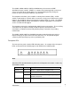
SG PCI Appliances (SG6xx Series) Note The SG PCI appliance range includes models SG630 and SG635. The SG PCI appliance is a hardware-based firewall and VPN server embedded in a 10/100 Ethernet PCI network interface card (NIC). It is installed into the host PC like a regular NIC, providing a transparent firewall to shield the host PC from malicious Internet traffic, and VPN services to allow secure remote access to the host PC.
The other is the host PC's IP address, which is configurable through the host operating system, identically to a regular NIC. This is the IP address that other PCs on the LAN see. It should be dynamically (DHCP) or statically configured to use the same gateway, DNS, etc. settings as a regular PC on the LAN. Note It is possible to configure the SG PCI appliance to run in masquerading mode. This is discussed in the chapter entitled Firewall.
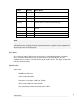
Location Activity Description Top right On Power is supplied to the SnapGear unit (top right). Flashing The SnapGear unit is operating correctly (bottom right). Flashing Data is being transmitted or received (top left). On The SnapGear unit is attached to the network. (Power) Bottom right (Heart beat) Top left (Network activity) Bottom left (Network link) Note If Heart beat does not begin flashing shortly after power is supplied, refer to Appendix D, Recovering From a Failed Upgrade.
10 Introduction
2. Getting Started This chapter provides step-by-step instructions for installing your SnapGear unit. These instructions are identical to those in the printed Quick Install Guide that shipped with your SnapGear unit. Upon completing the steps in this chapter, your SG gateway or rack mount appliance is installed in a network configuration similar that depicted in the figure to the right.
SG Gateway Appliance Quick Setup Unpack the SnapGear unit Check that the following items are included with your SnapGear unit: Power adapter SG CD Network cable On the rear panel of the SnapGear unit you will see network, serial and possibly USB ports, a Reset/Erase button, and a power inlet. The front panel of the SnapGear unit contains activity LEDs (lights) that vary slightly between models. These provide information on the operating status of the SnapGear unit.
Set up a single PC to connect to the SnapGear unit The SnapGear unit ships with initial network settings of: LAN IP address: 192.168.0.1 LAN subnet mask: 255.255.255.0 The SnapGear unit needs an IP address suitable for your LAN before it is connected. You may choose to use the SnapGear unit’s initial network settings above as a basis for your LAN settings.
Click Start > (Settings >) Control Panel and double-click Network Connections (or in 95/98/Me, double-click Network). Right-click Local Area Connection then select Properties. Note If there is more than one existing network connection, select the one corresponding to the network interface card to which the SnapGear unit is attached. Select Internet Protocol (TCP/IP) and click Properties (or in 95/98/Me, TCP/IP > your network card name if there are multiple entries) and click Properties.
Note If you wish to retain your existing IP settings for this network connection, click Advanced and Add the secondary IP address of 192.168.0.100, subnet mask 255.255.255.0. Set up the SnapGear unit’s password and LAN connection settings Launch your web browser and navigate to 192.168.0.1. Select Quick Setup Wizard from the center of the page. A login prompt is displayed.
The quick setup wizard is displayed. Changing the Hostname is not typically necessary. Select how you would like to set up your LAN connection, then click Next. Note You must select Manual configuration in order to enable the SnapGear unit’s built-in DHCP server. The SnapGear unit’s DHCP server automatically configures the network settings of PCs and other hosts on your LAN. Changes to the SnapGear unit’s LAN configuration do not take effect until the quick setup wizard has completed. 1.
If you have an existing DHCP server, and wish to rely on it to automatically configure the SnapGear unit’s LAN connection settings (not recommended), choose to Obtain LAN IP address from a DHCP server on LAN. Skip to the next step 3. 2. If you selected Manual configuration, some additional information is required. Otherwise, skip to the next step. 3. Enter an IP address and Subnet Mask for the SnapGear unit’s LAN connection.
Set up the SnapGear unit’s Internet connection settings Attach the SnapGear unit to your modem device or Internet connection medium. If necessary, give the modem device some time to power up. Select your Internet connection type and click Next. The options displayed differ depending on the connection type selected. If you are connecting using a Cable Modem, select your ISP, or Generic Cable Modem Provider if yours does not appear.
Set up the SnapGear unit’s switch Note This page will only display if you are setting up the SG560, SG565 or SG580. Otherwise skip to the next step. By default, the SnapGear unit’s switch A behaves as a conventional switching hub. However, it may be configured so that each port behaves as if it were physically separate from the others. Select a configuration for the SnapGear unit’s switch, then click Next.
Connect the SnapGear unit to your LAN Review your configuration changes. Once you are satisfied, click Finish to activate the new configuration. Note If you have changed the SnapGear unit’s LAN connection settings, it may become uncontactable at this point. This step describes how to set up the PCs on your network to access the SnapGear unit and the Internet. If you haven’t already done so, connect the SnapGear unit to your LAN.
If you do not want to use a DHCP server, proceed to Manual configuration of your LAN. Automatic configuration of your LAN If you selected Manual Configuration for the SnapGear unit’s LAN connection, and supplying DHCP Server Address Range, then the SnapGear unit’s DHCP server is already set up and running. Each PC on your LAN must now be set up to automatically obtain network settings. Click Start > (Settings >) Control Panel and double-click Network Connections (or in 95/98/Me, double-click Network).
Automatic configuration of your LAN using an existing DHCP server If you chose to have the SnapGear unit Obtain LAN IP address from a DHCP server on LAN, It is strongly recommended that you add a lease to your existing DHCP server to reserve the IP address you chose for the SnapGear unit’s LAN connection. If you chose to set the SnapGear unit’s LAN connection settings using Manual configuration, you may simply remove this address from the pool of available addresses.
Enter the following details: IP address is an IP address that is part of the same subnet range as the SnapGear unit’s LAN connection (if using the default settings, 192.168.0.2 – 192.168.0.254). Subnet mask is the subnet mask of the SnapGear unit’s LAN connection (if using the default settings, 255.255.255.0). Default gateway is the IP address of the SnapGear unit’s LAN connection (if using the default settings, 192.168.0.1).
The status LEDs on the front panel provide information on the operating status of the SnapGear unit. The Power LED is ON when power is applied. H/B (heart beat) flashes when the SnapGear unit is running. Each of the network ports has two LEDs indicating link, activity, and speed. In its factory-default state, the four status LEDs next to Power flash. If these LEDs do not behave in this manner before your SnapGear unit is attached to the network, perform a factory reset.
Next, modify your PC’s network settings to enable it to communicate with the SnapGear unit. Click Start > (Settings >) Control Panel and double-click Network Connections (or in 95/98/Me, double-click Network). Right-click Local Area Connection then select Properties. Note If there is more than one existing network connection, select the one corresponding to the network interface card to which the SnapGear unit is attached.
Note If you wish to retain your existing IP settings for this network connection, click Advanced and Add the secondary IP address of 192.168.0.100, subnet mask 255.255.255.0. Set up the SnapGear unit’s password and LAN connection settings Launch your web browser and navigate to 192.168.0.1. Select Quick Setup Wizard from the center of the page. A login prompt is displayed.
The Quick Setup wizard is displayed. Changing the Hostname is not typically necessary. Select how you would like to set up your LAN connection then click Next. Note You must select Manual configuration in order to enable the SnapGear unit’s built-in DHCP server. The SnapGear unit’s DHCP server automatically configures the network settings of PCs and other hosts on your LAN. Changes to the SnapGear unit’s LAN configuration do not take effect until the quick setup wizard has completed.
If you selected Manual configuration, some additional information is required. Otherwise, skip to the next step. Enter an IP address and Subnet Mask for the SnapGear unit’s LAN connection. Note Take note of this IP address and subnet mask, as you will need them later on. To enable the SnapGear unit’s built-in DHCP server, enter a range of addresses to hand out in DHCP Server Address Range.
Note If you have changed the SnapGear unit’s LAN connection settings, it may become uncontactable at this point. This step describes how to set up the PCs on your network to access the SnapGear unit and the Internet. Connect PCs and/or your LAN hub to switch A on the SnapGear unit. Set up the PCs on your LAN Each PC on your LAN must now be assigned an appropriate IP address, and have the SnapGear unit’s LAN IP address designated as its gateway and as its DNS server.
Select Internet Protocol (TCP/IP) and click Properties (or in 95/98/Me, TCP/IP > [your network card name] if there are multiple entries) and click Properties (in 95/98/Me, you may also have to click the IP Address tab). Check Obtain an IP address automatically, check Obtain DNS server address automatically and click OK (in 95/98/Me, reboot the PC if prompted to do so).
Ensure all PCs on the network are set up to automatically obtain network configuration as per Automatic configuration of your LAN, then restart them. Note The purpose of restarting the computers is to force them to update their automatically configured network settings. Alternatively you can use a utility such as ipconfig to release then renew the DHCP lease, or disable and re-enable the network connection.
Set up the SnapGear unit’s Internet connection settings Choose a port on the SnapGear unit for your primary Internet connection. Port C is used in this guide. Attach Port C to your modem device or Internet connection medium. If necessary, give the modem device some time to power up. Note If you have changed the SnapGear unit’s LAN connection settings, browse to the new LAN IP address. Select Network Setup from the Network Setup menu.
If you have a Direct Connection to the Internet (e.g. a leased line), enter the IP settings provided by your ISP. Note For detailed help for each of the options, please refer to the next chapter. After entering the appropriate details, click Finish. Quick setup is now complete.
SG PCI Appliance Quick Setup Unpack the SnapGear unit Check that the SG CD is included with your appliance: On the SnapGear unit is a single 10/100 network port, a Reset button, and four LEDs (lights). The LEDs provide information on the operating status of your SnapGear unit. The two LEDs closest to the network port indicate network link and network activity. The two LEDs furthest from the network port indicate Power and Heart Beat. The Heart Beat LED blinks when the SnapGear unit is running.
Set up your PC to connect to the web management console Note The following steps assume you want to set up your SnapGear unit in bridged mode, so that it sits between your PC and the LAN, transparently filtering network traffic. If you want to set up your SnapGear unit for NAT mode or to connect directly to your ISP, refer to Network Address Translation (NAT) on page 148. The SnapGear unit ships with initial network settings of: IP address: 192.168.0.1 Subnet mask: 255.255.255.
Select Use the following IP address and enter the following details: IP address: 192.168.0.100 Subnet mask: 255.255.255.0 Leave the Default gateway and DNS server addresses blank. Set up the SnapGear unit’s password and network connection settings Launch your web browser and navigate to 192.168.0.1. Select Network Setup from the Networking menu. A login prompt is displayed.
Note The new password takes effect immediately. You are prompted to enter it when completing the next step. In the row labeled Bridge, click the Modify icon. Note The purpose of this step is to configure the IP address for the web management console. For convenience, this is generally a free IP address on your LAN. If your LAN has a DHCP server running, you may set up the SnapGear unit and your PC to obtain their network settings automatically. Proceed to Automatic configuration.
Check DHCP assigned. Anything in the IP Address and Subnet Mask fields is ignored. Click Update. Click Start > (Settings >) Control Panel and double-click Network Connections. Right-click Local Area Connection (or appropriate network connection for the newly installed PCI appliance) and select Properties. Select Internet Protocol (TCP/IP) and click Properties and click Properties.
Check Obtain an IP address automatically, check Obtain DNS server address automatically and click OK. Attach your SnapGear unit’s Ethernet port to your LAN’s hub or switch. Quick setup is now complete. Manual configuration Ensure you have two free IP addresses that are part of the subnet range of your LAN, and ensure you know your LAN’s subnet mask, and the DNS server address and gateway address used by PCs on your LAN. Note Contact your network administrator if you are unsure of any of these settings.
Enter this address as the IP Address, and the subnet mask for your LAN as the Subnet mask. Ensure DHCP assigned is unchecked. You may also enter one or more DNS Server(s) and a Gateway address to be used by the SnapGear unit, not your PC, for access to the Internet. Typically this is not necessary, as only your PC needs to access the Internet. Click Update.
Enter the following details: IP address is the second free IP address that is part of your LAN’s subnet range. Subnet mask is you LAN’s subnet mask. Default gateway is your LAN’s default gateway IP address. Preferred DNS server is the IP address of the DNS server used by PCs on your LAN. Click OK. Attach your SnapGear unit’s Ethernet port to your LAN’s hub. Quick setup is now complete.
The SnapGear Management Console The various features of your SnapGear unit are configured and monitored using the management console. Follow the steps from the beginning of this chapter to set up your PC to access the management console. The main menu is displayed on the left hand side. Navigate your way around and get a feel for the SnapGear unit’s features by clicking the corresponding link in the main menu.
3. Network Setup This chapter describes the Network Setup sections of the web management console. Here you can configure each of your SnapGear unit’s Ethernet, wireless and serial ports. To access Network Setup, click the Network Setup under the Network Setup section of the main web management console menu. The QoS Traffic Shaping and IPv6 sections are also described towards the end of this chapter.
A network interface is configured by selecting a connection type from the Change Type pull-down menu. The current configuration can be viewed or modified by clicking the Edit icon. Clicking the Delete icon unconfigures a network interface; you are prompted to confirm this action. Multifunction vs. Fixed-function Ports Some SnapGear units have network ports with labels corresponding to the port’s function, i.e. LAN, DMZ and Internet/WAN. These are said to be fixed-function ports.
Note The switches’ ports can not be configured individually; a switch is configured with a single function only (e.g., LAN switch, DMZ switch). SG560, SG565 and SG580: Multifunction Ports The SG560, SG565 and SG580 have generically named Ethernet ports (ports A1, A2, A3, A4 and B). By default, switch A functions as a regular LAN switch, with network traffic passing freely between its ports. Typically, port B is used as your primary Internet connection.
Direct Connection A direct connection is a direct IP connection to a network, i.e. a connection that does not require a modem to be established. This is typically a LAN, DMZ or Guest connection, but may also be an Internet connection. Network settings may be assigned statically, or dynamically by a DHCP server. Note Direct connections may be added to a network bridge. For more information see Bridging on page 91. Network settings Click the Edit icon of the interface your wish to modify.
To have your SnapGear unit obtain its LAN network settings from an active DHCP server on your local network, check DHCP assigned. Note that anything in the IP Address, Subnet Mask and Gateway fields are ignored. You may also enter one or more DNS servers. To enter multiple servers, enter each IP address separated by commas. Firewall class The Firewall class setting controls the basic allow/deny policy for this interface. Allowed network traffic is accepted, denied network traffic is dropped.
If an Ethernet port is experiencing difficulties auto-negotiating with another device, Ethernet Speed and duplex may be set manually. On rare occasions, it may be necessary to change the Ethernet hardware or MAC Address of your SnapGear unit. The MAC address is a globally unique address and is specific to a single SnapGear unit. It is set by the manufacturer and should not normally be changed.
For aliases on interfaces that have the DMZ or Internet firewall class, you must also setup appropriate Packet Filtering and/or Port forwarding rules to allow traffic on these ports to be passed onto the local network. See the chapter entitled Firewall for details. IPv6 You must enable IPv6 under the Network Settings Connection tab for each connection that supports IPv6.
Do not continue until it has reached the line sync state and is ready to connect. Note For PPPoE/PPPoA connections, ensure your DSL modem is set to operate in bridged mode. Typically, for PPPoE connections, your DSL modem must be set to use LLC multiplexing/encapsulation. For PPPoA connections, your DSL modem must be set to use VC-based multiplexing/encapsulation.
Note If autodetection fails, it may be because your DSL modem is misconfigured for your connection type, or your DSL service has not yet been provisioned by your telco. Click Next to continue. PPPoE To configure a PPPoE or PPPoA connection, enter the user name and password provided by your ISP. You may also enter a descriptive Connection Name if you wish. Click Finish. By default, PPPoE connections are treated as “always on” and are kept up continuously.
PPTP To configure a PPTP connection to your ISP, enter the PPTP Server IP Address and a Local IP Address and Netmask for the SnapGear network port through which you are connecting to the Internet. The Local IP address is used to connect to the PPTP server and is not typically your real Internet IP address. You may also enter a descriptive Connection Name if you wish. Click Finish or Update.
The latter two settings are optional, but are generally required for normal operation. Multiple DNS addresses may be entered separated by commas. You may also enter a descriptive Connection Name if you wish. Click Finish or Update. Connection (dial on demand) You may choose to bring up a PPPoE/PPPoA DSL, dialout or ISDN connection only when PCs on the LAN, DMZ or Guest network (via a VPN tunnel) are trying to reach the Internet and disconnect again when the connection has been idle for a specified period.
Ethernet configuration See the section entitled Ethernet configuration under Direct Connection. Aliases See the section entitled Aliases under Direct Connection. Cable Modem To connect to the Internet using a cable Internet service, select Cable Modem from the Change Type pull-down menu for the interface that connects to your cable modem. Cable Modem connections have the interface firewall class of Internet.
Ethernet configuration See the section entitled Ethernet configuration under Direct Connection. Aliases See the section entitled Aliases under Direct Connection. Dialout and ISDN To connect to the Internet using a regular dialup or ISDN service, select Dialout from the Change Type pull-down menu for the interface that connects to your dialup modem or ISDN TA. Dialout and ISDN connections have the interface firewall class of Internet.
Port settings If necessary, you may set the SnapGear unit’s serial port Baud rate and Flow Control. This is not generally necessary. Static addresses The majority of ISPs dynamically assign an IP address to your connection when you dialin. However some ISPs use pre-assigned static addresses. If your ISP has given you a static IP address, click the Static Addresses tab and enter it in My Static IP Address and enter the address of the ISP gateway in ISP Gateway IP Address.
If you wish, you may enter a descriptive Connection Name. In the IP Address for Dial-In Clients enter an available IP address. This IP address must not already be in use on the network (typically the LAN) that the remote user is assigned while connected to the SnapGear unit. If you have configured several network connections, select the one that you want to connect remote users to from the IP Address for Dial-In Server pull-down menu. This is typically a LAN interface or alias.
Unencrypted Authentication (PAP): This is plain text password authentication. When using this type of authentication, the client passwords are transmitted unencrypted. Select the Required Encryption Level, access is denied to remote users attempting to connect not using this encryption level. Using Strong Encryption (MPPE 128 Bit) is recommended. Select the Authentication Database. This allows you to indicate where the list of valid clients can be found.
Connecting a dial-in client Remote users can dial in to the SnapGear unit using the standard Windows Dial-Up Networking software or similar. The following instructions are for Windows 2000/XP. Click Start > Settings > Network and Dial-up Connections and select Make New Connection. The network connection wizard guides you through setting up a remote access connection: Click Next to continue. Select Dial-up to private network as the connection type and click Next to continue.
Select Use dialing rules to enable you to select a country code and area code. This feature is useful when using remote access in another area code or overseas. Click Next to continue. Select the option Only for myself to make the connection only available for you.
Enter a name for the connection and click Finish to complete the configuration. Check Add a shortcut to my desktop to add an icon for the remote connection to the desktop. To launch the new connection, double-click on the new icon on the desktop. The remote access login screen appears as in the next figure. If you did not create a desktop icon, click Start > Settings > Network and Dial-up Connections and select the appropriate connection.
Failover, Load Balancing and High Availability Note This section applies to SG gateway and rack mount appliances only. The SnapGear unit supports a wide range of configurations through which you can use multiple Internet connections, and even multiple SnapGear units, to help ensure Internet availability in the event of service outage or heavy network load. The following Internet availability services are provided by the SnapGear unit. They may be configured individually, or in combination.
Note If you are using a SnapGear unit model SG560, SG565 or SG580, you may want to skip to information on establishing multiple broadband connetions. This information is in the section entitled Port Based VLANs on page 97. Once the Internet connections have been configured, specify the conditions under which the Internet connections are established.
Note Internet failover is not stateful, i.e. any network connections that were established through the failed primary connection must be re-established through the secondary connection. Edit connection parameters The first step of configuring failover is to set failover parameters for each connection. These parameters specify how to test whether a connection is up and functioning correctly. On the Network Setup page, click the Failover & H/A tab.
Select a Test Type. The Ping test is usually appropriate. Ping sends network traffic to a remote host at regular intervals, if a reply is received the connection is deemed to be up. Custom (advanced users only) allows you to enter a custom console command to run to determine whether the connection is up. This is typically a script you have written and uploaded to the SnapGear unit. Always Up means no test is performed, and Internet failover is disabled for this connection.
If you selected Custom, enter the custom Test Command that is used to test the connection, e.g.: myscript 5 10 ping -c 1 -I $if_netdev 15.1.2.3 Note If the Test Command exits with a return code of zero (0), the test is deemed to have passed and the connection is considered up. Otherwise, the connection is considered down. Also note that $if_netdev is replaced with the name of the network interface on which the test is being run, e.g. ppp0. If you selected Ping, enter an IP Address to Ping.
Recall that a connection level is one or more connections. These connections may be marked as Required or Enabled. Internet connections that are marked Disabled are not part of this connection level. A connection level is deemed to be up when all connections marked Required at that level are up, and at least one connection (marked Required or Enabled) at that level is up. On the Network Setup page, click the Failover & H/A tab, then Modify Levels.
This returns you to the main Connection Failover page. You’ll notice that ticks and crosses are display alongside each connection, describing how they are configured for each connection level. A red cross means Disabled, a green ticket means Enabled and a green tick with a small red plus means Required, Internet Load Balancing Once you have configured two or more Internet connections, you may enable Internet load balancing. Load balancing may be used in conjunction with Internet failover, or on its own.
Enabling load balancing Under the Failover & H/A tab, click Modify Levels. Check Load Balance for each connection to enable for load balancing. Click Finish. Note Load balancing settings are not specified for each failover level; load balancing occurs when any two or more load balancing connections are up. Limitations of load balancing Load balancing works by alternating outgoing traffic across Internet connections in a round robin manner.
VPN connections such as IPSec or PPTP tunnels are confined to a single Internet connection, as they are a single connection (that encapsulate other connections). Load balancing is not performed for incoming traffic. This scenario can be addressed using other solutions such as round robin DNS to alternate incoming connections between the two links.
In this scenario, SnapGear unit #1 is initially the master and therefore the default gateway for the local network and SnapGear unit #2 is the slave on standby. This may be because SnapGear unit #1 booted up before SnapGear unit #2, or SnapGear unit #2 may have previously failed, but has now come back online. Should SnapGear unit #1 lose LAN connectivity (e.g. someone accidentally powers it down), SnapGear unit #2 assumes the floating IP address and becomes the default gateway for the local network.
Later, SnapGear unit #1 comes back online as the slave. SnapGear unit #2 continues its role as the default gateway for the local network. Note Using the default high availability script, a high availability failover is not triggered by the master simply losing Internet connectivity. The master must become uncontactable to the slave via the local network segment for an HA failover to be triggered.
Note: Both devices should have identical High Availability configuration, including the list of interfaces, shared IP addresses, and the interface configured as the checked interface. DMZ Network Note Not available on the SG300, SG530, SG550 or SG PCI appliances. A DMZ (de-militarized zone) is a physically separate LAN segment, typically used to host servers that are publically accessible from the Internet. Servers on this segment are isolated to provide better security for your LAN.
By default, machines on the DMZ network have addresses in a private IP address range, such as 192.168.1.0 / 255.255.255.0 or 10.1.0.0 / 255.255.0.0. Real world addresses may be used on the DMZ network by by unchecking Enable NAT from DMZ interfaces to Internet interfaces under the Advanced tab. See the Network address translation section later in this chapter for further information.
If the servers on the DMZ servers have private IP addresses, you need to port forward the services. See the section called Incoming Access in the chapter entitled Firewall. Creating port forwarding rules automatically creates associated packet filtering rules to allow access. However, you can also create custom packet filtering rules if you wish to restrict access to the services. You may also want to configure your SnapGear unit to allow access from servers on your DMZ to servers on your LAN.
Caution is advised before allowing machines on a Guest network direct access to the Internet, particularly in the case of Guest wireless networks. This may result in unauthorized use of your Internet connection for sending spam, other malicious or illegal activities, or simply Internet access at your expense. Machines on the Guest network typically have addresses in a private IP address range, such as 192.168.2.0 / 255.255.255.0 or 10.2.0.0 / 255.255.0.0.
Wireless Note SG565 only. The SnapGear unit’s wireless interface may be configured as a wireless access point, accepting connections from 802.11b (11 Mbit/s) or 802.11g (54 Mbit/s) capable wireless clients. Typically, the SnapGear unit’s wireless interface is configured in one of two ways; with strong wireless security (WPA) to bridge wireless clients directly onto your LAN, or with weak wireless security as a Guest connection.
Warning We strongly recommend that the wireless interface be configured as a LAN connection only if wireless clients are using WPA based encryption/authentication. This is discussed in further detail later in this section. Configuring a Direct Connection is described in detail in the section entitled Direct Connection towards the beginning of this chapter. See the sections DMZ Network and Guest Network earlier in this chapter for further discussion of these network types.
Basic Security Method ESSID: (Extended Service Set Identifier) The ESSID is a unique name that identifies a wireless network. This value is case sensitive, and may be up to 32 alphanumeric characters. Broadcast ESSID: Enables broadcasting of the ESSID. This makes this wireless network visible to clients that are scanning for wireless networks.
Wireless security Encryption and authentication settings for your wireless network are configured under Access Point. Fields vary based on the security method you choose. If Security Method is set to None, any client is allowed to connect, and there is no data encryption. Warning If you use this setting, then it is highly recommended that you configure wireless interface as a Guest connection, disable bridging between clients, and only allow VPN traffic over the wireless connection.
Warning Due to flaws in the authentication protocol, this method reduces the security of the WEP key. It is recommended that you use Open System authentication instead. Open System or Shared Key: Allows clients to authenticate using either of the above two methods. WEP Key Length: This sets the length of the WEP keys to be entered below. It is recommended to use 128 bit keys if possible. WEP Key: Enter up to 4 encryption keys.
WPA-Enterprise Wi-Fi Protected Access uses the IEEE 802.1X protocol to provide authenticate the user and dynamically assign the encryption key via a RADIUS server. This is the recommended security method. The RADIUS server must be defined on the RADIUS page (see the RADIUS section of the chapter entitled System). WPA Encryption: Select the encryption algorithm, either TKIP (Temporary Key Integrity Protocol) or AES (Advanced Encryption Standard).
Select Allow authentication for MACs in the Access Control List to disallow all but the MAC addresses you specify, or Deny authentication for MACs in the Access Control List to allow all but the MAC address you specify. Click Update. Enter a MAC to allow or deny and click Add. A MAC may be removed from the list by clicking the corresponding Delete icon. Warning This is only a weak form of authentication, and does not provide any data privacy (encryption). MAC addresses may be forged relatively easily.
There are two common scenarios for WDS: bridging or repeating. WDS bridging is when an Access Point allows wireless clients to connect, and forwards packets from these clients to another Access Point. This is used to connect two wired Ethernet connections via a wireless link. WDS repeating is when an Access Point allows wireless clients to connect, and forwards packets from these clients to another Access Point.
1. Configure the wireless settings on the Access Point tab as normal. 2. Select the WDS tab. 3. Set Mode to Automatic. 4. Click Add and enter the MAC of the main Access Point. 5. Click the Connections tab, create a new Bridge. Select the Wireless interface, the LAN interface, and the WDS interface to all be on the bridge. Mode This is the mode that WDS is operating in, either Disable or Automatic. Disable – this disables WDS completely. Automatic – this enables bridging or repeating as appropriate.
Region: Select the region in which the access point is operating. This restricts the allowable frequencies and channels. If your region is not listed, select a region that has similar regulations. Protocol: 802.11b only: Wireless clients can only connect using 802.11b (11 Mbit/s). Note that most wireless clients which support 802.11g also support 802.11b. 802.11g only: Wireless clients can only connect using 802.11g (54 Mbit/s). Wireless clients that only support 802.11b are unable to connect. 802.
RTS incurs an overhead for transmitting, so enabling it when it is not needed decreases performance. Since the access point is in range of all wireless clients, you would not normally enable RTS for an access point. RTS Threshold: The minimum packet size for which RTS is enabled. Collisions are less likely for smaller packets, and so the overhead of using RTS for these may not be worthwhile. Enable Fragmentation: Normally, when a packet has an error, the entire packet must be retransmitted.
Click Wireless Configuration. Enter an appropriate ESSID and select a Channel for your wireless network. Enable Bridge Between Clients to allow wireless clients to intercommunicate, and there is generally no reason not to Broadcast ESSID. Take note of the ESSID and Channel, you need them to configure the wireless clients. Select WPA-PSK as the Security Method, select AES for WPA Encryption if your wireless clients support it, otherwise select TKIP.
Select Allow authentication for MACs in the Access Control List and click Apply. Select Add to add the MAC address of each wireless client you wish to allow to connect. Click Advanced. Ensure the Region has been set appropriately. You may also restrict the Protocol to 802.11b only or 802.11g only if you wish. Generally, the other settings should be left at their default values. Click Apply. Click the Connections tab.
Under the main table, select Bridge and click Add. Select your wired LAN connection from the Existing Interface Configuration pull-down box. This is the address to share between the interfaces. Click Next.
Alongside the wireless interface, check Bridged and select LAN from the Firewall Class pull-down menu. Click Finish. Note If your LAN interface was previously configured to obtain an IP address automatically from a DHCP server, the SnapGear unit now uses the MAC address of the wireless device when obtaining an IP address. You may have to update your DHCP server accordingly. Configure each wireless client with the Channel, ESSID, WPA Key and WPA Encryption method.
Another advantage is that network traffic not usually routed by unbridged interface, such as broadcast packets, multicast packets, and any non-IP protocols such as IPv6, IPX or Appletalk pass over the bridge to their destination host. Bridging network interfaces involves creating, then associating existing network interfaces with a Bridge interface. Warning You must trust all devices that are directly connected to bridged interfaces.
If you wish to transfer the IP address settings of an existing network connection to the bridge interface, select it from the Existing Interface Configuration pull-down menu. Click Next. Note As the SnapGear unit automatically directs network traffic, hosts on either side do not need to specify this IP address as a gateway to the networks connected to the bridge.
If you have multiple bridges on your network, you may want to Enable Spanning Tree Protocol. It allows the bridges to exchange information, helping elimate loops and find the optimal path for network traffic. Forwarding Delay is the time in seconds between when the bridge interface comes online and when it begins forwarding packets. This usually only occurs when the unit first boots, or the bridge configuration is modified.
When a packet is routed out the VLAN interface, the VLAN header is inserted and then the packet is sent out on the underlying physical interface. When a packet is received on the physical interface, it is checked for a VLAN header. If present, the router makes it appear as though the packet arrived on the corresponding VLAN interface. Once added, VLAN interfaces can be configured through the Network Setup > Connections table as if they were additional physical network interfaces.
Interface: Select the network interface on which to add the VLAN. VLAN ID: If this VLAN interface is to participate on an existing VLAN, the VLAN ID number must match the existing VLAN’s ID. Port / Mode: If this table is displayed, this interface has been enabled for port based VLANS; see the Port Based VLANs section later in this chapter. Click Update.
Port Based VLANs Note SG560, SG565 and SG580 only. The SG560, SG565 and SG580 have a VLAN-capable switch built in. This gives you the flexibility to either use it as a simple switch that allows access between all ports (this is the default), or use port based VLANs to control access between each individual port in the switch.
Limitations of port based VLANs There are few further limitations to keep in mind when using port based VLANs: The total bandwidth from the switch into the CPU is 100Mbits/s, which is shared between the 4 ports. This may limit the bandwidth available to a single port when perform general routing, packet filtering, and other activities. Port based VLANs can only be enabled if there are less than 16 total VLANs.
The following settings pertain to port based VLANs: Enable port based VLANs: Check to enable port based VLANs. Default port based VLAN ID: As the default VLAN is always untagged, typically you only need to change this from the default setting of 2 if you want another port to participate on an existing tagged VLAN with the ID of 2.
The following settings are displayed: Interface: The port based VLAN capable interface on which to add the VLAN. VLAN ID: If you are adding a VLAN interface to participate on an existing VLAN, enter its ID number here. Otherwise enter the next available VLAN ID; if the Default port based VLAN ID has been left at its default setting of 2, Port A2 uses VLAN ID 3, Port A3 uses VLAN ID 4, and so on. Note Some Cisco equipment uses tagged VLAN 1 for its own purposes.
Editing port based VLANs Once a VLAN has been added, you may edit the settings you entered in Adding port based VLANs by clicking its Edit icon in the main Network Setup > Connections table. Removing port based VLANs To remove a VLAN, click its Delete icon in the main Network Setup > Connections table. GRE Tunnels The GRE configuration of the SnapGear unit allows you to build GRE tunnels to other devices that support the Generic Routing Encapsulating protocol.
A bridged GRE tunnel is useful for transmitting packets across a VPN connection that would normally be dropped by IP routing. This includes broadcast packets, multicast packets and any non-IP protocol such as IP v6, IPX, or Apple Talk. Adding a GRE interface Under the Network Setup > Connections table, select GRE Tunnel and click Add. Ensure Enable is checked and enter a descriptive GRE Tunnel Name for this tunnel. Enter the address of the remote GRE endpoint in Remote Address, e.g.
2. Assign unused alias IP addresses to the LAN interfaces at both ends of the tunnel. 3. Create an IPSec tunnel between the alias IP addresses, using a prefix length for each network of /32. 4. Create a GRE tunnel for which the Local Address is the local LAN IP address, and the Remote Address is the remote LAN IP address. 5. Create bridges between the LAN interfaces and the GRE tunnel. To bridge the local and remote LAN over IPSec: 1.
Add the LAN connection to a bridge, as described in the section entitled Bridging earlier in this chapter. Give the LAN interface bridge a secondary address that is part of the network we want bridged across the tunnel. Adding an alias is described in Aliases in the section entitled Direction Connection earlier in this chapter. In this example, the Brisbane end uses an alias address of 10.254.0.1, and the Slough end uses an alias address of 10.254.0.2.
GRE Tunnel Name: to_slough Remote External Address: 10.254.0.1 Local External Address: 10.254.0.2 Firewall Class: LAN Click Finish to add the interface. Edit the bridge interface that you added at the beginning of these steps. Check Bridged for the GRE interface you have just added, and select a Firewall Class of LAN. Click Finish. At the Slough end, click Packet Filtering, click the Custom Firewall Rules, tab and add this custom firewall rule: iptables -I OUTPUT ! -o IPSec+ -d 10.254.0.
Ensure that the remote GRE end point responds to pings. Note that by default no packets are routed across the GRE tunnel unless there is a route set up on the GRE tunnel. Routes To configure the SnapGear unit’s advanced routing features, click the Routes tab on the Network Setup page. Static routes Here you can add additional static routes for the SnapGear unit. These routes are additional to those created automatically by the SnapGear unit configuration scripts. Click New to add a static route.
Route management Note Route management does not have full GUI configuration support. We recommend that only advanced users familiar with the Zebra routing daemon and/or the RIP, BGP or OSPF routing protocol attempt configuration of this feature. Advanced users may configure the SnapGear unit to automatically manage its routing tables, exchanging routes with other routers using RIP, BGP or OSPF protocol. Check Enable route management, select the desired Protocol and click Update.
password zebra!password In these examples,! denotes a descriptive comment # indicates a configuration line that is currently commented out, which you may want to uncomment depending on your network setup. In zebra.
#network eth2 ! Define neighbor routers to exchange RIP with if disabling multicast above in zebra.conf, or neighbors don't have multicast enabled #neighbor 192.168.45.238 #neighbor 192.168.45.231 ! Redistribute routing information for interfaces with RIP disabled redistribute connected ! Redistribute routing information from static route entries redistribute static ! Redistribute routing information from kernel route entries e.g. IPSec redistribute kernel Note RIP version 2 is used by default.
OSPF Note This example is adapted from the LARTC (Linux Advanced Routing & Traffic Control) dynamic routing howto, available from: http://lartc.org/howto/ LARTC is an invaluable resource for those wanting to learn about and take advantage of the advanced routing capabilities of Linux systems. OSPF stands for Open Shortest Path First, and some of its principal features as follows: Networks are grouped by areas, which are interconnected by a backbone area which will be designated as area 0.
The SG is configured to exchange routes with the routers named Atlantis, Legolas and Frodo. Ensure you have enabled OSPF under Route Management, then open zebra.conf and ospfd.conf for editing as described in the Route management section. In zebra.
! Uncomment and set telnet/vty passwords to enable telnet access on port 2604 #password changeme #enable password changeme ! Instruct ospfd about our network topology router ospf network 192.168.0.0/24 area 0 network 172.17.0.0/16 area 1 Restart route management to enable the updated configuration: Uncheck Enable route management, click Update, check Enable route management and click Update.
Note The AS numbers used in this example are reserved. Please get your own AS from RIPE if you set up official peerings. Ensure you have enabled BGP under Route Management, then open zebra.conf and bgpd.conf for editing as described in the Route management section. In zebra.conf, enter: hostname sg ! Uncomment and set telnet/vty passwords to enable telnet access on port 2602 #password changeme #enable password changeme In bgpd.
access-list local_nets deny any ! Our AS number router bgp 1 ! Our IP address bgp router-id 192.168.0.1 ! Announce our own network to other neighbors network 192.168.0.0/24 ! Advertise all connected routes (directly attached interfaces) redistribute connected ! Advertise kernel routes (manually inserted routes, IPSec) redistribute kernel ! Every 'router bgp' block contains a list of neighbors to which the router is connected: neighbor 192.168.1.1 remote-as 2 neighbor 192.168.1.
System To configure the SnapGear unit’s network system settings, click the System tab on the Network Setup page. These settings control the SnapGear unit’s identity on the network. Hostname The Hostname is a descriptive name for the SnapGear unit on the network. It is also used as the SNMP sysName field. By default, this is set to the model name of your SnapGear unit, e.g. SG710.
DNS To configure the SnapGear unit’s DNS settings, click the DNS tab on the Network Setup page. These settings control the SnapGear unit’s network name services. The DNS configuration information is stored in /etc/config/dnsmasq.conf. For a complete list of the options that may be stored in this file run the following command: # dnsmasq --help DNS proxy The SnapGear unit can be configured to run a domain name server (DNS) proxy.
Dynamic DNS A dynamic DNS service is useful when you don’t have a static IP address, but need to remain contactable by hosts on the Internet. Dynamic DNS service providers such as TZO.com and dyndns.org can register an Internet domain name that points to your IP address no matter how often it changes. Whenever its Internet IP address changes, the SnapGear unit alerts the dynamic DNS service provider and the domain name records are updated appropriately.
DHCP Server Note To configure your SnapGear unit as a DHCP server, you must set a static IP address and netmask on the network interface on which you want the DHCP server to run; see the Direct Connection section of the chapter entitled Network Connections. To begin configuring the SnapGear unit’s DHCP server, select DHCP Server from the Network Setup section of the web management console’s main menu.
Enter the DNS Address to issue the DHCP clients. If this field is left blank, the SnapGear unit’s IP address is used. Leave this field blank for automatic DNS server assignment. If your SnapGear unit is configured for DNS masquerading, you should either leave this field blank, or enter the IP address of the LAN port of the SnapGear unit. Optionally enter a Domain Name suffix to issue DHCP clients. Optionally enter the IP address of the WINS server to be distributed to DHCP clients in the WINS Address field.
There is a trashcan icon to delete the address from the list of addresses to manage. You may also Free addresses that have been leased by hosts on your network. This causes the lease to expire immediately, leaving the address available for the next host that requests IP configuration. The Status field displays one of three states: Reserved: The address is reserved for the particular host defined by hostname and MAC address. Free: The address is available to be handed out to any DHCP client host.
Reserving IP addresses You may reserve IP addresses for particular hosts, identifying them by hostname and MAC address. These reserved hosts are also added to the /etcconfig/hosts file (static hosts) for DNS purposes; see the Static Hosts section of this chapter. This allows the computers on the LAN to use the names even if there is no other DNS server around. This is useful for sites that are too small to run a DNS/WINS server.
The Subnet is the network on which DHCP server is handing out addresses. Free Addresses displays the number of remaining available IP addresses that can be distributed. If this value is 0, you may need to increase the number of IP addresses to hand out. DHCP Proxy The DHCP proxy allows the SnapGear unit to forward DHCP requests from the LAN to an external server for resolution. This allows both static and dynamic addresses to be given out on the LAN just as running a DHCP server would.
Web Cache Note SG565, SG575, SG580, SG635 and SG rack mount appliances only. Web browsers running on PCs on your LAN can use the SnapGear unit’s proxy-cache server to reduce Internet access time and bandwidth consumption. A proxy-cache server implements Internet object caching. This is a way to store requested Internet objects (i.e., data available via HTTP, FTP, and other protocols) on a server closer to the user's network than on the remote site.
If you are using a Network Share or Local Storage (recommended, see below), it is generally best to set this to 8 Megabytes. Otherwise, start with a small cache (8 Megabytes or 16 Megabytes) and gradually increase it until you find a safe upper limit where the SnapGear unit can still operate reliably. Storage The web cache is capable of utilizing a storage device attached via the USB port, or a network share to provide backing store for the cache.
Network storage share Note Network Storage share and Local Storage cannot be used at the same time. Enabling one will automatically disable the other. A network share is a shared folder or drive on a local Windows PC, or a PC running another operating system capable of SMB sharing (such as a Linux PC running the SAMBA service). Refer to your operating system’s documentation for details on creating a network share. What follows are some basic instructions for creating a network share under Windows XP.
Launch Windows Explorer (Start > (All) Programs > Accessories > Windows Explorer) and open up a folder or drive to dedicate as a network share for use by the SnapGear unit’s web cache. Begin by disabling simple file sharing for this folder. From the Tools menu, select Folder Options. Click the View tab and under the Advanced settings section uncheck Use simple file sharing (Recommended). Click OK. Next, share the folder. Right-click the folder and select Sharing and Security.
Under the Network Share tab, check Use share. Enter the location of the network share in the format: \\HOSTNAME\sharename Enter the maximum size for the cache in Cache size. Warning The size of this cache should be at least as big as the Cache size on the Main tab and not be more than 90% of the space available to the network share. Enter the User name and Password for a user that can read and write to the network share. If you allowed Full Control to Everyone, you may leave these blank.
Click Advanced, Peers, then New. Tthe messages transmitted by a cache to locate a specific object are sent to Sibling caches, which are placed at the same level in the hierarchy. Then, the caches placed at the Parent level are queried if the replies from sibling caches did not succeed. Enter the host or IP address of an ICP-capable web cache peer in Host, then select its relationship to the SnapGear unit’s web cache (as described above) from Type and click Apply.
ICAP RESPMOD server is the URL for an ICAP server's RESPMOD service. This allows an ICAP server to modify web transaction responses, i.e. to process traffic that is returned from an external web server, e.g. for virus scanning. It must begin with icap://, e.g.: icap://192.168.0.10:1344/respmod You may choose to Bypass ICAP server if uncontactable. If the ICAP server is not responding to requests, web transactions are allowed as normal.
Log File Rotation Time (minutes) specifies how often the logs are checked for rotation. Log File Rotations specifies how many log file rotations should be stored. The minimum default of 1 means 2 files will be kept: the current log file and the previous log file. The maximum of 9 will mean 10 files will be kept. Web cache with access control To allow the web cache to operate simultaneously with access controls, including content filtering and anti-virus, you must make some configuration changes.
QoS autoshaper The Auto Traffic Shaper uses a set of inbuilt traffic shaping rules to attempt to ensure low latency on interactive connections, while maintaining fast throughput on bulk transfers. Click Edit next to the network interface on which you wish to enable the autoshaper. Click Enable and enter the Outbound Speed (upstream speed) of this interface’s network connection in megabits per second. Click Finish.
Check Enable Traffic Shaping, select a Default priority and click Submit to enable this feature. The Default priority is assigned to all network services other than those specifically added below. To add a service, click New then New again. Select the Protocol and Port on which this service runs. Select Priority for this service then click Finish.
IPv6 Check Enable IPv6 to enable IPv6 routing and packet filtering. Support for IPv6 is currently limited. Note You must also enable IPv6 for each connection that supports IPv6. See the section entitled Direct Connection towards the beginning of this chapter.
If you use an external SIP service such as the Gizmo Project or Skype, you typically do not need to use the SIP proxy. These services use STUN (Simple Traversal of UDP through NATs) to facilitate communication from behind a masquerading firewall. The SIP proxy listens on UDP port 5060 for SIP requests (this is the standard SIP port and should not generally need to be changed), and UDP ports 7070-7079 for RTP traffic (the actual voice data). Configuring the SIP proxy Check Enabled.
4. Firewall The SnapGear unit is equipped with a fully featured, stateful firewall. The firewall allows you to control both incoming and outgoing access, so that PCs on local networks can have tailored Internet access facilities while being shielded from malicious attacks from external networks. The SnapGear unit’s stateful firewall keeps track of outgoing connections (e.g. a PC on your LAN requesting content from a server on the Internet) and only allows corresponding incoming traffic (e.g.
Administration services The following figure shows the Administration Services page: By default the SnapGear unit runs a web administration server, a Telnet and an SSH service. Access to these services can be restricted to specific interfaces. Only Administrative users with the Login access control are able to connect via telnet. SSH provides for secure encrypted communication whereas telnet is completely unencrypted.
Warning If you do want to allow administrative access on interfaces other than LAN Interfaces, there are several security precautions you should take. See the note in the next section for details. Also consider remote administration using a VPN connection as an alternative to opening a hole in the firewall, PPTP in particular is well suited to this task. You can also select to Accept echo request (incoming port) on Internet interfaces.
Note Changing the web server port number is recommended if you are allowing Internet access to the Management Console. This may help hide the web management console from casual web surfers who type your SnapGear units Internet IP address into a web browser. Ideally, you should use packet filter rules (see the Packet Filtering section later in this chapter) to restrict who has access for remote administration (i.e.
Once valid SSL certificates have been uploaded or created, A valid SSL certificate has been installed is displayed. The Snap Gear administrative web server can then operate in one of 3 modes: Normal (HTTP) and SSL (HTTPS) web server access Disable SSL (HTTPS) web server access (HTTP only) Disable normal (HTTP) web server access (HTTPS only) To access the web management console securely using SSL encryption, the URL becomes https:// instead of http:// (e.g. https://10.0.0.1).
Select the appropriate Country and certificate key length from the Generate an RSA key of pull-down menu. All other fields but Host name (Common Name) are optional; they are used to create the certificate’s distinguished name. Generating a certificate usually takes a few minutes, exact time depends on the model of SnapGear unitand the key length. When the certificate has been created, A valid SSL certificate has been installed is displayed under the Web Server tab.
Service groups A network service is defined by a protocol and port. Protocol may be either TCP, UDP, ICMP or IP, and port may be any valid network port number (i.e. between 1 and 65535), e.g. HTTP (web) uses the TCP protocol, with a default port of 80. Network packets may be matched by destination service. Click the Service Groups tab. Any services that have already been defined are displayed. Click New to add a new service group, or select an existing service group and click Modify.
Addresses Addresses are a single IP address, or range of IP addresses, or a DNS hostname. Network packets may be matched by source or destination address. Click the Addresses tab. Any addresses that have already been defined are displayed. Click New to add a new address, or select an existing address and click Modify. There is no need to add addresses for the SnapGear unit’s interfaces, these are predefined.
Adding or modifying an address is shown in the following figure: You may either add a Single Address or Range or DNS Hostname. You may also group previously added addresses together by defining an Address Group to simplify your firewall ruleset. Select how you would like to add the address or addresses, and click New. Either enter the DNS Hostname, the IP Address or address range and an optional descriptive Name, or select the addresses to group and enter a descriptive Name. Click Finish.
Packet Filtering Packet filter rules match traffic based on a combination of the source and destination address, incoming and outgoing interface, and destination service. Matched packets may be allowed or disallowed. Packet filter rules Click Packet Filter Rules. Click New to add a new filter rule. Any rules that have already been defined are displayed. You may Edit or Disable/Enable these rules by clicking the appropriate icon.
The Action specifies what to do if the rule matches. Accept means to allow the traffic. Drop means to disallow the traffic. Reject means to disallow the traffic, but also send an ICMP port unreachable message to the source IP address. None means to perform no action for this rule. This is useful for a rule that logs packets, but performs no other action. Type controls which incoming and outgoing interface options are available. Forward means filter forwarded packets only, i.e.
The Outgoing Interface is the interface/network port that the SnapGear unit routes the network traffic out of. Set this to None to match traffic originating from the SnapGear unit itself. The Source Address is the address that the traffic is arriving from. The Destination Address is the address that the traffic is destined to. Warning The previous four fields may be set to Any. Any does not match traffic sent or received by the SnapGear unit itself, only traffic passing through it.
Once you have created a packet filtering rule, you may specify rate limiting settings. These settings are useful for preventing a service from becoming unavailable should many connection attempts occur in a short period of time (e.g. in the case of a denial of service (DOS) attack). Packets that exceed the specified limit can be accepted, rejected or dropped, and can be logged. Click the Modify icon next to the rule that you wish to rate limit, and click the Rate Limit tab.
Log Prefix specifies the text to be placed at the start of the log message. This can be used to make it easier to identify which rules are being matched when inspecting the system log. Custom firewall rules The Custom Firewall Rules and Custom IPv6 Firewall Rules tabs allow firewall experts to view the current firewall rules and add custom iptables firewall rules. Note Only experts on firewalls and iptables are able to add effective custom firewall rules (further reading can be found at http://www.
1-to-1 NAT is a combination of destination NAT and source NAT. Both destination NAT and source NAT rules are created for full IP address translation in both directions. This can be useful if you have a range of IP addresses that have been added as interface aliases on the SnapGear unit’s WAN interface, and want to associate one of these external alias IP addresses with a single internal, masqueraded computer.
Note The example shown in the screenshot above forwards the SSH (secure shell) protocol to an internal server (barry’s server). SSH allows encrypted remote access, typically to a server running Linux, BSD or another Unix-like operating system. In this example, port 2222 is used rather than the standard SSH port of 22. This is to allow remote access using SSH to the SnapGear unit itself, which runs an SSH server on port 22.
This rule is applied to packets that match the critera described by the next four fields. Destination Address The destination address of the request, this is the address that is altered Protocol The service of the packet, which may be a TCP or UDP destination port, an IP protocol, or an ICMP message type Ports The destination service port or ports of the request, note that many public ports may be forwarded to a single internal port The next two fields describe how matching packets should be altered.
Port forwarding to an internal mail server The following is an example of using port forwarding to allow hosts on the Internet to send and receive mail using a mail server on your LAN. Warning Precautions must be taken when configuring the mail server, otherwise you may become susceptible to such abuse as unauthorized relaying of unsolicited email (spam) using your server. Configuration of the email server is outside the scope of this manual.
Check one or both of IMAP4 (E-Mail) if your server supports IMAP mail retrieval and POP3 (E-Mail) if your server supports POP3 mail retrieval. Enter smtp in Other TCP Ports. This is the protocol remote clients use for sending mail via the server. Click Finish. Click NAT, the Port Forwarding tab, and then New. Click Advanced at the bottom of the page. Enter Mail server In Descriptive Name.
Leave Enable checked. Select your Internet connection in Destination Address. Enter the translated port of the packet. If you leave this blank, then the port will be unchanged. You cannot translate the port for IP protocols or ICMP messages. You should normally set this field to the port of the service on your internal server. You cannot translate the port if Services is set to a predefined service.
Click Source NAT. Any rules that have already been defined are displayed, you may Edit or Disable/Enable these rules by clicking the appropriate icon. Click New to add a new rule. You may also add a new rule above an existing one by clicking the Add Above icon, or below with Add Below. Note The first matching rule determines the action for the network traffic, so the order of the rules is important. You can use the Move Up and Move Down icons to change the order.
Outgoing Interface Enter the interface that the packet to masquerade behind, typically Internet. Source Address Enter the address from which the request originated, typically be a private address on the LAN or DMZ. Destination Address Enter the destination address of the request. Services Enter the destination service port or ports of the request. The next fields describe how matching packets should be altered. To Source Address Enter the address to replace the Source Address.
1-to-1 NAT This creates both a source NAT and destination NAT rule for mapping all services on an internal, private address to an external, public address. Note After adding a 1-to-1 NAT rule, you must manually create packet filter rules to allow incoming packets on the public address. Click Source NAT. Any rules that have already been defined are displayed; you may Edit or Disable/Enable these rules by clicking the appropriate icon. Click New to add a new rule.
Enable Uncheck to temporarily disable this rule. Private Address Enter the private address to change. Public Address Enter the public address, typically a WAN interface alias. Public Interface Select the interface on which the public address resides, this is typically Internet. Note When adding a rule, you may either use Predefined addresses that have been added under Definitions, or click New to manually enter an address.
The displayed options apply to the firewall classes, not to the ports with these names. That is, the LAN interface options apply to all interfaces that are configured with a LAN connection type, not just to the port labelled as LAN. It is strongly recommended that you leave Enable NAT from LAN/VPN interfaces to Internet interfaces checked. Typically, this is required to allow Internet access from the LAN.
Note The port forwarding rules set up via the UPnP Gateway are temporary. The list of configured UPnP port forwarding rules is cleared should the SnapGear unit be power cycled, or should the internal or external interface become unavailable. The UPnP Gateway is intended for transitory application port forwarding, such as those established by some versions of Microsoft Messenger for file transfers.
Enter an arbitrary Description of service, the Name or IP address of the computer hosting this service on your network, the External Port number for this service and the Internal Port number for this service. Select whether the service uses the TCP or UDP protocol. Click OK. This rule now appears on the SnapGear unit UPnP page, under Current UPnP Port Mappings. Connection Tracking Connection tracking keeps a record of what packets have passed through the unit, and how they relate to each other.
Note Implementations of protocols such as H.323 can vary, so if you are experiencing problems you can try disabling the module. Check Enable Connection Logging to log connections to the system log as they are established and expire; however, this may result in a lot of log messages if you have a large or busy network. Check Enable Flood Rate Limiting to enable flood rate limiting for new connections on Internet interfaces.
Intrusion Detection Note The SG300, SG530, SG550, SG560, SG570, and SG630 provide Basic Instrusion Detection and Blocking only. The SnapGear unit provides two intrusion detection systems (IDS): the lightweight and simple-to-configure Basic Intrusion Detection and Blocking, and the industrial strength Advanced Intrusion Detection and Prevention. These two systems take quite different approaches.
These attacks can potentially be detected and prevented using an intrusion detection system. Basic Intrusion Detection and Blocking (IDB) Click the IDB tab to configure basic Intrusion Detection and Blocking (IDB). IDB operates by offering a number of services to the outside world that are monitored for connection attempts. Remote machines attempting to connect to these services generate a system log entry providing details of the access attempt, and the access attempt is denied.
Warning This is a word of caution regarding automatically blocking UDP requests. Because an attacker can easily forge the source address of these requests, a host that automatically blocks UDP probes can be tricked into restricting access from legitimate services. Proper firewall rules and ignored hosts lists significantly reduce this risk. Trigger count before blocking specifies the number of times a host is permitted to attempt to connect to a monitored service before being blocked.
The Basic button installs a bare bones selection of ports to monitor while still providing sufficient coverage to detect many intruder scans. The Standard option extends this coverage by introducing additional monitored ports for early detection of intruder scans. The Strict button installs a comprehensive selection of ports to monitor and should be sufficient to detect most scans.
The primary advantage of running Snort IDS (Snort) in front of the firewall is that it sees unfiltered network traffic, and is therefore able to detect a wider range of attacks. The primary advantage of running Snort IPS (IPS) behind the firewall is that suspicious network traffic can be disallowed, rather than simply flagged as suspicious and allowed to pass. Snort uses a combination of methods to perform extensive network traffic analysis on the fly.
Rule sets are sets of defined patterns or rules used for the detection of attacks. These are grouped by type such as ddos, exploit, backdoor, netbios, etc. Each group encompasses many attack signatures. The full list of signatures can be viewed at the Snort web site (http://www.snort.org). Note The more rule sets that are selected, the greater load is imposed on the device. Therefore a conservative rather than aggressive approach to adding rule sets should be followed initially.
Sensor Name is an arbitrary string that is prepended to the log output. This may be useful if you have deployed more than one intrusion detection system. Enter the User name and Password required for authentication to the remote database. Click Submit to apply your changes. Setting up the analysis server Specific open source tools are required to be installed on the analysis server for a straightforward evaluation.
PHPlot graph library for charts written in PHP http://www.phplot.com/ BASE analysis console http://secureideas.sourceforge.net/ Snort is running as an IDS sensor on the SnapGear unit, logging to the MySQL database on the analysis server. The Downloads section of the BASE website contains detailed documents that aid in installing the above tools on the analysis server.
Access Control and Content Filtering The access control web proxy allows you to control access to the Internet based on the type of web content being accessed (Content or Webwasher), and which user or workstation is accessing the Internet content (Require user authentication, IP Lists). This is useful to minimize inappropriate Internet use.
The Enable Access Control checkbox enables/disables the entire access control subsystem. This box must be checked for any access control operation to take place. The Require User Authentication checkbox determines if users are asked for a user name and password when attempting to access the web through the SnapGear unit. The Default Action field defines the behavior when none of the settings positively allow or block access.
User authentication Check Require user authentication if you want to require users to authenticate themselves before browsing the web. When attempting to access a web site on the Internet, the browser displays a dialog similar to the following: Note To add or remove access controls user accounts, select Users from the main menu and click the Local Users tab. Access controls users should generally have only Internet Access (Access Controls) checked, with all other access permissions unchecked.
Note Each browser on the LAN now has to be set up to use the SnapGear unit’s web proxy. Browser setup The example given is for Microsoft Internet Explorer 6. Instructions for other browsers should be similar; refer to their user documentation for details on using a web proxy. From the Internet Options menu, select Tools. From the LAN Settings tab, select LAN Settings. Check Use a proxy server for your LAN… and Bypass proxy server for local addresses. All other options should remain unchecked.
In the row labeled HTTP, enter your SnapGear unit’s LAN IP address in the Proxy address to use column, and 81 in the Port column. Leave the other rows blank. In the Exceptions text box, enter your SnapGear unit’s LAN IP address. Click OK, OK and OK again. ACL Access may be Blocked or Allowed by the Source (LAN) IP address or address range, the Destination (Internet) host’s IP address or address range, or the Destination Host’s name. Addresses are added through Definitions > Addresses.
Web lists Access is denied to any web address (URL) that contains text Added under URL Block List, e.g. entering xxx blocks access to any URL containing xxx, e.g.: http://www.xxx.com, http://xxx.example.com or www.test.com/xxx/index.html The Allow List also enables access to URLs containing the specified text. Note Defining large numbers of URL fragments to match against can result in a significant slowing down of WWW accesses.
The top level page has a checkbox Block Unscanned Hosts which defines the behavior for a host which hasn't been scanned or is not defined to be scanned. The Simultaneous Probes setting specifies the maximum number of different hosts that should be scanned together. The Minimum Inter Probe Delay specifies a minimum number of seconds between scans of a single host. It also specifies the maximum time for changes to take effect.
Script Management Click the Script Management tab for management and testing of installed NASL scripts. NASL is the part of the Nessus vulnerability scanner that performs the majority of the vulnerability checks. By default, newly uploaded scripts will appear here but will not be available for use with a policy enforcement group. To make a script available, it is necessary to either manually enable it or to fully validate it.
In the Upload NASL script field, either enter or Browse… to the NASL script file you wish to upload. This file will be uploaded to the SnapGear unit and made available in the Script Management page. Content filtering Note Content filtering is only available after you have registered your SnapGear unit and activated your content filtering license (sold separately). See the Obtaining a content filtering license section below. Content filtering allows you to limit the types of web-based content accessed.
All new content filtering subscriptions are for the Webwasher service. The old content filtering system is maintained for backwards compatibility for existing subscribers only. If you have been given a single license key, you have a subscription to the original Content system. If you have been given a certificate and private key, you have a subscription to the new Webwasher system. Webwasher Check Enable content filtering and paste in your Certificate and Private key.
Under the Categories tab, select the Blocked Categories to block access to. Under the Reports tab, enter your User name and Password and click View Reports to view reporting on blocked accesses, etc. Before content filtering can be enabled, both a certificate and a private key must be provided. Under the Certificates tab, enter content fitler certificate. Under the Private Key tab, enter the content filtering private key.
Checking Enable Cache stores recently accessed pages’ ratings locally, to lower the response time the next time the page is accessed. It is recommended that you leave this checked. Blocked requests are submitted to the central content filtering server. The user attempting to access blocked content can be identified either through User Accounts (see User Authentication earlier in this chapter) or the IP Address of their machine. Click the Reports tab to connect to the central content filtering server.
The SnapGear unit’s antivirus capabilities shield your LAN from viruses that propagate through email, the web and FTP. An antivirus subscription is not required and virus definitions are automatically kept up-to-date. Note If you are seeing messages in your system log stating your clamav is OUTDATED, it may be possible to update the SG's virus scanning engine (ClamAV) by upgrading your SnapGear unit’s firmware.
Check Enable. The Database mirror is the host from which the signature database is updated. Unless there is a specific host from which you want the SnapGear unit to retrieve signature updates, leave this at the default setting of database.clamav.net. Select the frequency to Check for updates from the database mirror. The checks are quick and shouldn't cause a noticeable decrease to performance unless an update is necessary.
Create a new user account: Note We recommend that you create a special user account to be used by the SnapGear unit for reading and writing to the network share. If you have an existing account or wish to make the network share readable and writeable by everyone, you may skip the next step. To create an account, click Start > Control Panel > User Accounts > Create a new account. Type a name for the new account, e.g. sguser, and click Next.
Begin by disabling simple file sharing for this folder. From the Tools menu, select Folder Options. Click the View tab and under the Advanced settings section uncheck Use simple file sharing (Recommended). Click OK. Next, share the folder. Right-click the folder and select Sharing and Security. Select Share this folder and note the Share name, you may change this to something easier to remember if you wish. Finally, to set the security permissions of the newly created network share, click Permissions.
Local storage Note SG565 only. Attach a USB storage device to one of the SnapGear unit’s USB ports. Under the Storage > Local Storage tab, select the partition or device to use from the Device pull-down menu, and click Submit. POP email The SnapGear unit can scan email being sent by PCs on your LAN before delivering it to the destination mail server. Note Scanning of IMAP and web-based email is not supported.
Check Transparent. If all of your internal email clients (such as Microsoft Outlook) are retrieving email from a single mail server only, enter it as the Default POP server. Uncheck Allow connections to other POP servers. If most, but not all, of your internal email clients are retrieving email from a single mail server, enter this as the Default POP server. Check Allow connections to other POP servers.
If there is no single mail server from which most of your internal email clients are retrieving email, leave Default POP server blank and check Allow connections to other POP servers. Note For each of the email clients that is not retrieving email from the default POP server (this may be all email clients), the email client’s POP (or POP3) user name setting must be in the form of user@mail.isp.com, rather than simply user – user is the POP login, and mail.isp.com is the POP mail server.
Note For each of the email clients for which to scan incoming mail, the email client’s POP3 user name setting must be in the form of user@mail.isp.com, rather than simply user – user is the POP3 login, and mail.isp.com is the POP3 mail server. Additionally, the email client’s incoming/POP3 email server setting must be sent to the SnapGear unit’s LAN IP address (e.g. 192.168.0.1). Typically it is not necessary to adjust the POP3 protocol Request timeout.
When Inform requesting server of rejected mail is enabled the SnapGear unit rejects incoming mail that is detected to have a virus, and informs the requesting SMTP server that the mail has been dropped. This is the default and recommended behavior. When Inform requesting server of rejected mail is disabled the SnapGear unit accepts and then subsequently drops incoming mail that is detected to contain a virus.
FTP The SnapGear unit can scan files downloaded using FTP for viruses. Check Virus check FTP downloads. Typically there is no need to change the Proxy port on which the transparent proxy listens for connections. If an FTP connection is idle for the number of seconds specified by No activity timeout, it is automatically disconnected. Increase this only if you are experiencing time-outs during FTP sessions. You may specify the Maximum simultaneous connections to allow.
5. Virtual Private Networking Virtual Private Networking (VPN) enables two or more locations to communicate securely and effectively, usually across a public network (e.g. the Internet) and has the following key traits: Privacy - No one else can see what you are communicating . Authentication - You know who you are communicating with. Integrity - No one else can tamper with your messages/data.
PPTP and L2TP The SnapGear unit includes a PPTP and an L2TP VPN server. These allow remote Windows clients to securely connect to the local network. PPTP or L2TP are also commonly used to secure connections from a guest network; see the Guest Network section in the chapter entitled Network Setup. PPTP VPN Server To setup a PPTP connection from a remote Windows client to your SnapGear unit and local network: Enable and configure the PPTP VPN server.
Check Enable PPTP Server. Enter the IP Addresses to give to remote hosts. This must be a free IP address, or a range of free IP addresses, from the network (typically the LAN) that the remote users are assigned while connected to the SnapGear unit. If you have configured several network connections, select the one that you want to connect remote users to from the IP Address to Assign VPN Server pull-down menu. This is typically a LAN interface or alias. Select the weakest Authentication Scheme to accept.
Select the Required Encryption Level. Access is denied to remote users attempting to connect not using this encryption level. Strong Encryption (MPPE 128 Bit) is recommended. Select the Authentication Database. This allows you to indicate where the list of valid clients can be found. You can select from the following options: Local: Use the local database defined on the Local Users tab of the Users page. You must enable the Dial-in Access option for the individual users that are allowed dial-in access.
Your Internet IP address is displayed on the Network Setup page. If your ISP has not allocated you a static IP address, consider using a dynamic DNS service. Otherwise you must modify the PPTP client configuration each time your Internet IP address changes. For details on configuring dynamic DNS, refer to the DNS section of the chapter entitled Network Setup. Ensure the remote VPN client PC has Internet connectivity. To create a VPN connection across the Internet, you must set up two networking connections.
Select Connect to a private network through the Internet and click Next. This displays the Destination Address window: Enter the SnapGear unit’s Internet IP address or fully qualified domain name and click Next.
Enter an appropriate name for your connection and click Finish. Your VPN client is now set up and ready to connect. Windows XP PPTP client setup Login as Administrator or with administrator privileges. From the Start menu, select Settings and then Network Connections. Click Create New Connection from the Network Tasks menu to the left.
Select Connect to the network at my workplace and click Next. Select Virtual Private Network connection and click Next. Choose a Connection Name for the VPN connection, such as your company name or simply Office. Click Next.
If you have set up your computer to connect to your ISP using dial up, select Automatically dial this initial connection and your dial-up account from the pull-down menu. If not, or if you wish to manually establish your ISP connection before the VPN connection, select Do not dial the initial connection. Click Next. Enter the SG PPTP appliance’s Internet IP address or fully qualified domain name and click Next.
Enter a user name and password added in the Configuring user accounts for VPN server section and click Connect. L2TP VPN Server To setup an L2TP/IPSec connection from a remote Windows XP client to your SnapGear unit and local network: Enable and configure the L2TP VPN server. Configure IPSec tunnel settings. Set up VPN user accounts on the SnapGear unit and enable the appropriate authentication security. Configure the VPN clients at the remote sites.
Check Enable L2TP Server. Enter the IP addresses to give to remote hosts. This must be a free IP address, or a range of free IP addresses, from the network (typically the LAN) that the remote users are assigned while connected to the SnapGear unit. If you have configured several network connections, select the one that you want to connect remote users to from the IP Address to Assign VPN Server pull-down menu. This is typically a LAN interface or alias.
Select the Required Encryption Level — access is denied to remote users attempting to connect not using this encryption level. Using Strong Encryption (MPPE 128 Bit) is recommended. Select the Authentication Database. This allows you to indicate where the list of valid clients can be found. You can select from the following options: Local: Use the local database defined on the Local Users tab of the Users page.
Note Only one shared secret tunnel may be added. The one shared secret is used by all remote clients to authenticate. Select x.509 Certificate Tunnel to use x.509 certificates to authenticate the remote client against a Certificate Authority's (CA) certificate. The CA certificate must have signed the local certificates that are used for tunnel authentication.
If adding an x.509 Certificate Tunnel, select the Local Certificate that you have uploaded to the SnapGear unit. Enter the Client Distinguished Name; it must match exactly the distinguished name of the remote party's local certificate to successfully authenticate the tunnel. Distinguished name fields are listed Note Certificates need to be uploaded to the SnapGear unit before a tunnel can be configured to use them (see Certificate Management in the IPSec section later in this chapter).
Select Connect to the network at my workplace and click Next. Select Virtual Private Network connection and click Next. Choose a Connection Name for the VPN connection, such as your company name or simply Office. Click Next.
If you have set up your computer to connect to your ISP using dial up, select Automatically dial this initial connection and your dial up account from the pull-down menu. If not, or you wish to manually establish your ISP connection before the VPN connection, select Do not dial the initial connection. Click Next. Enter the SG PPTP appliance’s Internet IP address or fully qualified domain name and click Next.
To authenticate using an x.509 Certificate Tunnel, you must first install the local certificate. The distinguished name of this local certificate must match the name entered in Client Distinguished Name when configuring the x.509 certificate tunnel on the SnapGear unit. See Certificate Management and Using certificates with Windows IPSec in the IPSec section later in this chapter for details on creating, packaging and adding certificates for use by Windows IPSec.
Select PPTP VPN Client or L2TP VPN Client from the VPN section of the main menu. Any existing client tunnels are displayed alongside icons to Enable/Disable, Delete, and Edit them. To add a new tunnel, click New. Ensure Enable is checked, and enter: A descriptive Name for the VPN connection. This may describe the purpose for the connection. The remote PPTP or L2TP Server IP address to connect to. A User name and Password to use when logging in to the remote VPN.
A PPTP status icon appears in the system tray on the bottom right hand side of your computer, informing you that you are connected. You can now check your e-mail, use the office printer, access shared files and computers on the network as if you were physically on the LAN. Note Depending on how your remote network is set up, some additional configuration may be required to enable browsing the network (such as Network Neighborhood or My Network Places).
Quick Setup This section uses the Quick Setup to connect the two sites together. For more control over the configuration options, see Set Up the Branch Office on page 215. Enable IPSec Select IPSec from the VPN section of the main menu. A page similar to the following is displayed. Check the Enable IPSec checkbox then click Quick Setup.
Fill in the Tunnel name field with your name for the tunnel. The name must not contain spaces or start with a number. In this example, enter Headquarters. Leave the Enable this tunnel checkbox checked. Enter The remote party’s IP address, which is the IP address of the remote party’s IPSec endpoint. For a remote party that has a dynamic IP address, click Predefined. Enter the Local Network that will have access to the remote network.
Enter the Remote Distinguished Name, which is the list of attribute/value pairs contained in the certificate of the remote peer.
When making a certificate based tunnel between Secure Computing SnapGear units, you can obtain the Distinguished Name of a remote device's Certificate from the Details column of the appropriate local certificate on the Certificate Lists tab of the IPSec page. Enter the Local Certificate, which is the list of local certificates that have been uploaded for x.509 authentication. Select the required certificate to be used to negotiate the tunnel.
Warning It may be necessary to reduce the MTU of the IPSec interface if large packets of data are not being transmitted. Configure a tunnel to connect to the headquarters office To create an IPSec tunnel, click the IPSec link on the left side of the web management console and then click the Advanced under Tunnel List. A window similar to the following displays: Tunnel settings page Fill in the Tunnel name field with a description for the tunnel. The name must not contain spaces or start with a number.
Note Select an interface other than the default gateway when you have more than one Internet connection or have configured aliased Internet interfaces, and require the IPSec tunnel to run on an interface other than the default gateway. From the Keying drop-down, select the type of keying for the tunnel to use.
DNS hostname address to static IP address DNS hostname address to DNS hostname address DNS hostname address to dynamic IP address From the Local address drop-down, select the type of IPSec endpoint this SnapGear unit has on the interface on which the tunnel is going out. The SnapGear unit can either have a static IP, dynamic IP or DNS hostname address.
In this example, select the Preshared Secret option. Click Next to configure the Local Endpoint Settings. Local endpoint settings Leave the Initiate Tunnel Negotiation checkbox checked. Note This option is not available when the SnapGear unit has a static IP address and the remote party has a dynamic IP address. Enter the Optional Endpoint ID of the SnapGear unit. This ID is used to authenticate the SnapGear unit to the remote party.
Note If the remote party is a SnapGear unit, the ID must have the form abcd@efgh. If the remote party is not a SnapGear unit, refer the interoperability documents on the SG Knowledge Base (http://www.cyberguard.com/snapgear/knowledgebase.html) to determine what form it must take. In this example, enter: branch@office Leave the IP Payload Compression checkbox unchecked. If compression is selected, IPComp compression is applied before encryption. Check the Dead Peer Detection checkbox.
Authentication Key is the ESP Authentication Key. It must be of the form 0xhex, where hex is one or more hexadecimal digits. The hex part must be exactly 32 characters long when using MD5 or 40 characters long when using SHA1 (excluding any underscore characters). This field appears when Manual Keying has been selected. Encryption Key is the ESP Encryption Key. It must be of the form 0xhex, where hex is one or more hexadecimal digits.
Enter the Internet IP address of the remote party in The remote party's IP address field. In this example, enter: 209.0.0.1. The Optional Endpoint ID is used to authenticate the remote party to the SnapGear unit. The remote party's ID is optional if it has a static IP address and uses Preshared Secrets for authentication. It becomes a required field if the remote party has a dynamic IP or DNS hostname address or if RSA Digital Key Signatures are used for authentication.
OU Organizational Unit CN Common Name N Name G Given name S Surname I Initials T Personal title E E-mail Email E-mail SN Serial number D Description TCGID [Siemens] Trust Center Global ID The attribute/value pairs must be of the form attribute=value and be separated by commas. For example : C=US, ST=Illinois, L=Chicago, O=SecureComputing, OU=Sales, CN=SG550. It must match exactly the Distinguished Name of the remote party's local certificate to successfully authenticate the tunnel.
Authentication Key field is the ESP Authentication Key. However, this applies to the remote party. It must be of the form 0xhex, where hex is one or more hexadecimal digits. The hex part must be exactly 32 characters long when using MD5 or 40 characters long when using SHA1 (excluding any underscore characters). It must use the same hash as the SnapGear unit’s authentication key. This field appears when Manual Keying has been selected. Encryption Key field is the ESP Encryption Key.
The Rekeyfuzz value refers to the maximum percentage by which the Rekeymargin should be randomly increased to randomize rekeying intervals. The Key lifetimes for both Phase 1 and Phase 2 are dependent on these values and must be greater that the value of “Rekeymargin x (100 + Rekeyfuzz) / 100.” In this example, leave the Rekeyfuzz as the default value of 100%. Enter a secret in the Preshared Secret field. Keep a record of this secret as it is used to configure the remote party's secret.
Local Certificate pull-down menu contains a list of the local certificates that have been uploaded for x.509 authentication. Select the required certificate to be used to negotiate the tunnel. This field appears when x.509 Certificates has been selected. Phase 2 settings page Specify the Local Networks and Remote Networks to link together with the IPSec tunnel. For the Local Network, you may use a Predefined network, or enter a Custom network address.
Select a Phase 2 Proposal. Any combination of the ciphers, hashes, and Diffie Hellman groups that the SnapGear unit supports can be selected. The supported ciphers are DES, 3DES and AES (128, 196 and 256 bits). The supported hashes are MD5 and SHA and the supported Diffie Hellman group are 1 (768 bit), 2 (1024 bit) and 5 (1536 bits). The SnapGear unit also supports extensions to the Diffie Hellman groups to include 2048, 3072 and 4096 bit Oakley groups.
Select the Internet interface the IPSec tunnel is to go out on. In this example, select default gateway interface option. Select the type of keying for the tunnel to use. In this example, select the Aggressive mode with Automatic Keying (IKE) option. Select the type of IPSec endpoint this SnapGear unit has. In this example, select the static IP address option. Select the type of IPSec endpoint the remote party has. In this example, select the dynamic IP address option.
Phase 1 settings page Set the length of time before Phase 1 is renegotiated in the Key lifetime (s) field. In this example, leave the Key Lifetime as the default value of 3600 minutes. Set the time for when the new key is negotiated before the current key expires in the Rekeymargin field. In this example, leave the Rekeymargin as the default value of 600 seconds. Set the maximum percentage by which the Rekeymargin should be randomly increased to randomize rekeying intervals in the Rekeyfuzz field.
Tunnel List Connection Once a tunnel has been configured, an entry with the tunnel name in the Connection field is shown. Note You may modify, delete or disable/enable a tunnel by clicking on the corresponding Edit, Delete or Enable/Disable icon. Remote party The Remote Party which the tunnel is configured to connect to is defined either by its Endpoint ID, IP Address or Distinguished Name. Click Remote Party to sort the tunnel list by the remote party ID/name/address.
o IPSec is disabled. o The tunnel is disabled. o The tunnel could not be loaded due to misconfiguration. Negotiating Phase 1 indicates that IPSec is negotiating Phase 1 to establish the tunnel. Aggressive or Main mode packets (depending on tunnel configuration) are transmitted during this stage of the negotiation process. Negotiating Phase 2 indicates that IPSec is negotiating Phase 2 to establish the tunnel. Quick mode packets are transmitted during this stage of the negotiation process.
Diffie Hellman Groups Loaded lists the Diffie Hellman groups and Oakley group extensions that can be configured for both Phase 1 and Phase 2 negotiations. Connection Details lists an overview of the tunnel's configuration. It contains the following information: An outline of the tunnel's network setup. In this example, it is 192.168.2.0/24===209.0.0.2(branch@office)...209.0.0.1===192.168.1.0/24 Phase 1 and Phase 2 key lifetimes (ike_life and IPSec_life respectively). In this example, they are both 3600s.
Negotiation State reports what stage of the negotiation process the tunnel is in. In this example it has initiated and sent the first aggressive mode packet (AI1) and is expecting its response (AR1) in the line STATE_AGGR_I1 (sent AI1, expecting AR1). Once the Phase 1 has been successfully negotiated, the status displays ISAKMP SA established. Once the Phase 2 has been successfully negotiated, the status displays IPSec SA established. The tunnel is then established and running.
If you do not have access to certificates issued by a certificate authority (CA), you may create self-signed certificates; see Creating certificates further on. The OpenSSL application The remainder of this section requires OpenSSL application, run from a Windows command prompt (Start > Run > type cmd) or Linux shell prompt. A Windows version of OpenSSL is provided in the openssl directory of the SG CD.
openssl pkcs12 -nomacver -nocerts -in pkcs12_file -out local_private_key.pem .. where pksc12_file is the PKCS12 file issued by the CA and local_private_key.pem is the local private key certificate to be uploaded into the SnapGear unit. When the application prompts you to Enter Import Password, enter the password used to create the certificate. If none was used simply press enter. When the application prompts you to Enter PEM pass phrase, choose a secure pass phrase that is greater than 4 characters long.
Create the CA certificate, omit the –nodes option if you want to use a password to secure the CA key: openssl req -config openssl.cnf -new -x509 -keyout rootCA/ca.key -out rootCA/ca.pem -days DAYS_VALID -nodes .. where DAYS_VALID is the number of days the root CA is valid for. Create local certificate pairs For each local certificate you wish to create, there are two steps. First, create the certificate request: openssl req -config openssl.cnf -new -keyout cert1.key -out cert1.
To install the new PCKS12 file, cert1.p12, on Windows XP, open up the Microsoft Management Console (Start > Run > then type mmc). Add the Certificate Snap-in (File > Add/Remove Snap-in > Add > select Certificates > Add > select the account level you want the certificates installed for (i.e. current user vs. all users) (> Local Computer) > Close > OK. Double-click Certificates to open the store. Select the Personal store. Import new certificate (Action > All Tasks > Import). Locate cert1.p12.
Certificates have time durations in which they are valid. Ensure that the certificates uploaded are valid and that the Date and Time settings have been set correctly on the SnapGear unit. IPSec Failover Note SG560, SG565, SG570, SG575, SG580, SG710 only. The SnapGear unit can be configured to failover and fall forward between IPSec connections. Two common scenarios are described below.
Keying: Aggressive mode (IKE) Local address: Static IP address Remote address: Dynamic IP address Route to remote endpoint: Internet port's gateway Remote required endpoint ID: primary@branch Local network: 192.168.1.0/255.255.255.0 Remote network: 192.168.2.0/255.255.255.
Tunnel name: SecondaryLink Enable this tunnel: Unchecked Local interface: Default gateway interface Keying: Aggressive mode (IKE) Local optional endpoint ID: secondary@branch The remote party's IP address: 209.0.1.1 Local network: 192.168.2.0/255.255.255.0 Setup an unused aliased IP address on the LAN interface of both the Headquarter and Branch Office SGs. For example: Headquarters SG configuration: Alias IP address: 192.168.11.1 Alias subnet mask: 24 Branch office SG configuration: Alias IP address: 192.
Local network: 192.168.11.1/255.255.255.255 Remote network: 192.168.12.1/255.255.255.255 Phase 2 key lifetime (sec): 7200 Branch Office SG configuration: Tunnel name: PrimaryLinkTest Enable this tunnel: Unchecked Local Interface: Default gateway interface Keying: Aggressive mode (IKE) Local optional endpoint ID: primarytest@branch The remote party's IP address: 209.0.0.1 Local network: 192.168.12.1/255.255.255.255 Remote network: 192.168.11.1/255.255.255.255 Manually edit the ifmond.
retry_delay 5 test_delay 5 test ifretry 2 5 ping -I 192.168.2.1 192.168.1.1 -c 3 connection secondarylink parent conn-eth1 start IPSec auto --add SecondaryLink start IPSec auto --up SecondaryLink stop IPSec whack --delete --name SecondaryLink maximum_retries 2147483647 retry_delay 5 test_delay 5 test ifretry 2 5 ping -I 192.168.2.1 192.168.1.
Setup an IPSec tunnel between the primary Internet IP Addresses (209.0.0.1 <> 210.0.0.1). Default values are used in the configuration unless otherwise specified below: Headquarters SG configuration: Tunnel name: PrimaryLink Local interface: Internet port Route to remote endpoint: Internet port's gateway The remote party's IP address: 210.0.0.
Local interface: DMZ port Route to remote endpoint: DMZ port's gateway The remote party's IP address: 210.0.1.1 Local network: Address of DMZ port Remote network: Remote endpoint Branch Office SG configuration: Tunnel name: SecondaryLink Enable this tunnel: Checked Local interface: DMZ port Route to remote endpoint: DMZ port's gateway The remote party's IP address: 209.0.1.
GRE tunnel for primary link: GRE tunnel name: PrimaryLink Remote address: 209.0.0.1 Local address: 210.0.0.1 Firewall class: LAN GRE tunnel for secondary link: GRE tunnel name: SecondaryLink Remote address: 209.0.1.1 Local address: 210.0.1.1 Firewall class: LAN Manually edit the ifmond.conf on both the Headquarter and Branch Office SG to configure for IPSec failover and fall forward. Headquarters SG ifmond.
retry_delay 5 test_delay 5 connection primary_ping parent conn-gre1 maximum_retries 2147483647 retry_delay 5 test_delay 5 test ifretry 2 5 ping -I 209.0.0.1 210.0.0.1 -c 3 connection secondary_ping parent conn-gre2 maximum_retries 2147483647 retry_delay 5 test_delay 5 test ifretry 2 5 ping -I 209.0.1.1 210.0.1.1 -c 3 service service-IPSec group primary_ping group secondary_ping Branch Office SG ifmond.
parent secondary_ping start route add -net 192.168.1.0 netmask 255.255.255.0 dev gre2 stop route del -net 192.168.1.0 netmask 255.255.255.0 dev gre2 maximum_retries 2147483647 retry_delay 5 test_delay 5 connection primary_ping parent conn-gre1 maximum_retries 2147483647 retry_delay 5 test_delay 5 test ifretry 2 5 ping -I 210.0.0.1 209.0.0.1 -c 3 connection secondary_ping parent conn-gre2 maximum_retries 2147483647 retry_delay 5 test_delay 5 test ifretry 2 5 ping -I 210.0.1.1 209.0.1.
Symptom: Tunnel is always down even though IPSec is running and the tunnel is enabled. Possible Cause: The tunnel is using Manual Keying and the encryption and/or authentication keys are incorrect. The tunnel is using Manual Keying and the SnapGear unit’s and/or remote party's keys do not correspond to the Cipher and Hash specified. Solution: Configure a correct set of encryption and/or authentication keys.
Symptom: Tunnel goes down after a while Possible Cause: The remote party has gone down. The remote party has disabled IPSec. The remote party has disabled the tunnel. The tunnel on the SnapGear unit has been configured not to rekey the tunnel. The remote party is not rekeying correctly with the SnapGear unit. Solution: Confirm that the remote party has IPSec and the tunnel enabled and has an Internet IP address. Ensure that the SnapGear unit has rekeying enabled.
Possible cause: Windows network browsing broadcasts are not being transmitted through the tunnel. Solution: Set up a WINS server and use it to have the remote hosts resolve names to IP addresses. Set up LMHOST files on remote hosts to resolve names to IP adresses. Symptom: Tunnel comes up but the application does not work across the tunnel. Possible cause: There may be a firewall device blocking IPSec packets. The MTU of the IPSec interface may be too large. The application uses broadcasts packets to work.
The SnapGear unit supports two kinds of port tunnels. HTTP Tunnels are port tunnels that send data using the HTTP protocol, and are not encrypted. HTTP tunnels are not encrypted. They can be useful when the SnapGear unit is behind a firewall that only allows outgoing HTTP connections and blocks all other traffic. SSL Tunnels are port tunnels that send data using an encrypted SSL pipe.
The following field is displayed for SSL Tunnel Server only: You may specify the Protocol to use when negotiating the SSL connection. Leave this set to Raw when incoming connections are from a tunnel client. Setting Protocol to another value allows the tunnel server to accept connections directly from an SSL client other than a tunnel client, e.g. a mail client configured to use POP3 over SSL.
If the HTTP proxy is a buffering proxy, then enter the Proxy Buffer Size. Otherwise set this field to 0. You may also specific the timeout before sending padding to fill up the buffer size in Proxy Padding Timeout. The following field is displayed for SSL Tunnel Server only: You may specify the Protocol to use when negotiating the SSL connection. Leave this set to Raw connecting to a tunnel server.
6. USB Note SG565 only. The SG565 has two USB (Universal Serial Bus) ports to which you can attach USB storage devices (e.g. hard drives, flash drives, card readers), USB printers, USB network devices and USB narrowband (non-DSL) modems. A USB hub may be used if you need to attach more than two USB devices simultaneously. Note USB DSL modems are not supported at this time.
This section describes how to set up the SnapGear unit for network attached storage. For information on using a USB mass storage device as a print spool, refer to the USB Printers section. Share the storage device Select Shares from the Networking section of the main menu. Click the Storage tab. All USB Devices or device Partitions that are available to share are listed along with their Sizes and for previously configured shares, their Share Names.
Browsable: Display an icon for the network when browsing the network from a Windows PC. To access the network share when this is unchecked, the user must manually enter the address in the address bar (e.g. \\SG565\public\). Writable: The network share is writable, i.e. users can modify and create new files. Public: A login and password is not required to access the network share. Users: A valid login and password is required to access the network share. Selecting this option displays a list of users.
Join a Windows workgroup The next step is to configure your SnapGear unit to join your Window workgroup or domain. Select Network Setup from the Networking menu. Click the Advanced tab. Under the Unit Workgroup heading, enter the name of your Windows workgroup or domain and click Apply. Typically, this name is UPPERCASE. Once NAS devices or printers have been shared, your SnapGear unit becomes visible to other members. To test this, browse the workgroup from a Windows PC that is a workgroup member.
Partitioning a USB mass storage device Warning This procedure is intended for experts and power users only. The standard Linux command line tools are present on the SnapGear unit for partitioning (fdisk) and creating filesystems (mkfs) on an attached USB mass storage device. Alternatively, you may use the standard Windows tools or a third party utility such as PartitionMagic to partition a USB mass storage device before attaching it to the SnapGear unit.
Command (m for help): p Disk /dev/sda: 5 heads, 50 sectors, 1024 cylinders Units = cylinders of 250 * 512 bytes Device Boot Start End Blocks Id 1 1024 127975 b /dev/sda1 System Win95 FAT32 Delete any existing partitions by typing d the entering the partition number, e.g. enter 1 to delete /dev/sda1. Create a new partition by typing n then p for primary, then the partition number. Note The SnapGear unit support primary partitions only, so you are limited to four partitions.
Repeat the process for each partition to want to create. For the last partition, the default last cylinder is generally be fine.
mkfs.vfat –F 32 /dev/sda1 then mkfs.vfat –F 32 /dev/sda2 From the web management console, select Advanced from the System menu, and click Reboot. The partitions are now ready to use. USB Printers The SnapGear unit’s print server allows you to share attached USB printers with your LAN. After the printer server has been configured, the SnapGear unit and printer are displayed when you browse your Windows workgroup or domain.
Select Shares from the Networking section of the main menu. Click the Printing tab. Locate the printer to share and click its Edit icon. Enter a short descriptive Name for the printer. This is the name that is displayed when browsing your Windows workgroup or domain, and the name of the queue for LPR / LPD connections. Click Finish. Set up the print spool By default, the SnapGear unit spools incoming print jobs into memory (RAM) before sending them to the printer.
Otherwise, attach the USB mass storage device and select the device or device partition on which to store the print spool from the Spool pull-down menu under the Printing tab. Note You may simultaneously use a USB mass storage device or device partition as a print spool and a Network Attached Storage device. However, the spool directory becomes visible (as spool) and there is a higher chance of the device filling up, causing print jobs to fail.
Select A network printer, or a printer attached to another computer and click Next. Select Browse for a printer and click Next. Locate the SnapGear unit by expanding your Windows workgroup and locating the SG by its hostname. The hostname is set on the SnapGear unit under Network Setup > Advanced > Unit Hostname. Select the printer and click Next.
You may receive a warning about the SnapGear unit automatically installing print drivers on your PC. Ignore it, the SG does not install print drivers automatically. If a dialog is displayed to inform you that no appropriate print driver could be found on the SnapGear unit, click OK. Select the appropriate driver for your printer.
Select your printer model and click OK. If your printer model is not listed, click Have Disk and Browse again. Drivers for several different printers and different operating systems are often distributed together by the manufacturer, so there may by several different .inf files. Follow the onscreen instructions to install the printer driver. This varies from printer to printer. Note If you cannot locate the appropriate .
LPR / LPD setup Note This information is generally not relevant for Windows network environments. Once the print server has been set up, the SnapGear unit also listen on the standard LPR / LPD network port (TCP 515) for incoming print jobs. Set up your LPR client to print to a remote LPD queue as specified by your operating system’s documentation. The queue name is the Name you specified during Set up print server.
Disable Advanced Printing Features by clicking Control Panel > Printers and Faxes > right-click printer > Properties > Advanced > and uncheck Enable Advanced Printing Features. Disable Bidirectional Support by clicking Control Panel > Printers and Faxes > rightclick printer > Properties > Ports > and uncheck Enable Bidirectional Support. Printing still fails Here are a few more troubleshooting suggestions: Check whether you can print a single page from Notepad (Start > Programs > Accessories > Notepad).
7. System Date and Time Note For details on how the SnapGear unit stores and retrieves the date and time between reboots, see the appendix entitled System Clock. We recommend setting the SnapGear unit’s clock to the correct date and time, otherwise system log message time stamps do not match the time of the event. If you are using certificates for SSL or IPSec, it is especially important that you set the date and time correctly, as all certificates include an expiry date after which they do not function.
Network time Select Date and Time from the System section of the main menu, then the NTP Time Server tab. Check the Enabled box under the NTP Time Server heading and click Submit. Local hosts can now synchronize their clocks to the SnapGear unit’s by specifying the SnapGear unit’s IP address as their network time server. In Windows XP, this setting is available under Start (> Settings) > Control Panel > Date and Time > Internet Time.
Select Date and Time from the System section of the main menu, then the NTP Time Server tab. Enter the IP Address of the NTP server. Select Peer from the Type drop down box. Click Add. Locality Select Date and Time from the System section of the main menu, then the Locality tab. Select your local Region and click Submit. The system clock subsequently displays local time. By default, the system clock displays UTC.
Remote backup/restore Click the Remote backup/restore tab. To back up your configuration, enter and confirm a Password with which to protect this file and click Submit. Save the file in a safe place. Note Ensure this is a hard to guess password, as all passwords including IPSec passwords and private keys are downloaded into your saved configuration. Ensure your password is easy to remember, if this password is lost there is no way to restore your configuration.
Enter a Description for this configuration. It is not necessary to include the time and date in the description, they are recorded automatically. Note Each configuration snapshot stores a single configuration only, existing configuration snapshots on the SnapGear unit are not saved inside any subsequent snapshots. Restore locally backed up configurations by click its corresponding Restore icon in the Restore or Delete Configuration.
Users This section details adding administrative users, as well as local users for PPTP, L2TP or dial-in access, or access through the access control web proxy (see the Access Control section in the chapter entitled Firewall). Administrative users Administrative user accounts on a SnapGear unit allow administrative duties to be spread amongst a number of different people according to their level of competence and trust.
You may specify the following access controls for each administrative user. The Login control provides the user with telnet and ssh access to the command-line administration interface of the SnapGear unit. The Administration control provides the user with the ability to make changes to the SnapGear unit’s configuration via the web-based administration interface. This should only be provided to trusted users who are permitted to configure and reconfigure the unit.
Warning A user with Encrypted save / restore all access can conceivably create an encrypted config file with an arbitrary root password that they can restore, thus granting them Administration privileges. Therefore, grant Encrypted save / restore all only to users that you trust with Administration access. The Change Password control provides the user with the ability to change their password. Click Finish to apply your changes.
Enter a User name (login name), an optional Description, and enter and confirm a Password. For dial-in, PPTP and L2TP users, you may also optionally enter a Domain name if your network has a Windows domain server. You may specify the following access controls for each local user. The Dial-in Access control provides the user with the authority to connect to the SnapGear unit’s dial-in server.
To test your configuration click the Test RADIUS tab and enter the user name and password of a valid user. A RADIUS request is sent to the server and the result are displayed. If no response is received, carefully check the IP address of the RADIUS server and also the shared secret configuration for this device (NAS). Note This test uses a simple PAP request. If your RADIUS server is configured only for CHAP, you may receive an Access Denied message, even for a valid user name/password combinationo.
Management The SnapGear unit may be management remotely using Secure Computing Global Command Center (GCC), Secure Computing Centralized Management Server (CMS) or Simple Network Management Protocol (SNMP). GCC To enable remote management by a Secure Computing Global Command Center server, check Enable Central Management. Enter the Global Command Center Server Host Name. Enter the Global Command Center Server IP Address.
Clicking Enrol allows you to register this unit with the Global Command Center server using the standard mechanism. Click Rapid Deploy to make use of Rapid Deployment. The SnapGear unit will need to be added using the "Sign Up Firewalls" dialog from the "SG Firewalls" section of the "Security Device" Objects. Note Ensure that you have network access and have the Global Command Center server configured appropriately before enabling central management.
Specify the shared Authentication Key with which to authenticates this device against the CMS. This must be the same as the snmp_community configuration setting for CMS. It should be something hard to guess. When configured for centralised management, the device periodically sends a "ping" (SNMP trap) back to the CMS to indicate that it is alive. Back-to-base ping interval (s) specifies the interval in seconds between these pings. This must be less than the max_alive_interval configuration setting for CMS.
Enter the name of a community that is allowed read-write access in Read-Write Community. You may optionally include an IP address or network to restrict who is allowed access. You may optionally include an OID to restrict the fields that are accessible. Warning The community name is equivalent to a password, and is sent in plain text in every SNMP packet. Anyone who knows the community name is able to modify settings on this device.
Log output is color coded by output type. General information and debug output is black, warnings and notices are blue, and errors are red. The Display pull-down menu underneath the log output allows you to filter the log output to display this is based on output type. Appendix B contains for details on interpreting log output and configuring advanced log rules. Local syslog By default all messages are recoreded in the System Log.
Enter the Remote Port on which the remote syslog server is listening for syslog messages. Typically, the default is correct. Set the Filter Level to only send syslog messages at this level or above. You may also Include extended ISO date, which is prepended to syslog messages before being sent. Click Submit to save your changes. Email delivery Syslog log messages may be sent to an email account. This allows you to keep system log messages persistently. Check Enable Email Logging.
Specify the number of seconds to wait after recieving a system log message before sending an email in Delay to Send (s). This allows multiple system log messages to accumulate before sending an email containing them all. Messages per Email is the maximum number of system log messages that are allowed to accumulate before sending the email. The default setting of 0 means unlimited, and is typically appropriate for all systems but those that experience heavy traffic. Click Submit to apply your changes.
Advanced The following options are intended for network administrators and advanced users only. Warning Altering the advanced configuration settings may render your SnapGear unit inoperable. Reboot and Reset Rebooting does not erase your SnapGear unit’s configuration, however network connections such as your Internet connection, VPN tunnels, etc. are terminated and reestablished when the device is up and running again.
Reset button Another method to clear the SnapGear unit’s stored configuration information is by pushing the reset button on the back panel of the SnapGear unit twice. A bent paper clip is a suitable tool for performing this procedure. This is particularly useful should the SnapGear unit become uncontactable, e.g. due to misconfiguration. Pushing the reset button twice clears all stored configuration information, reverts all settings to the factory defaults, and reboots the SnapGear unit.
There are two primary methods available for performing a flash upgrade, Netflash and Flash upgrade via HTTP. Remote upgrades may also be performed using TFTP if you have a TFTP server at the remote site, see Flash upgrade via TFTP. During the upgrade, the front panel LEDs on the SnapGear unit flash in an in-and-out pattern. The SnapGear unit retains its configuration information with the new firmware. Warning If the flash upgrade is interrupted (e.g.
Note Although we recommend it, this program is not supported by Secure Computing. Download the binary image file (.sgu). Contact SG technical support for instructions on obtaining this file. Place this file in the directory your TFTP is serving files from, usually: /tftpboot/ Establish a telnet or ssh connection to the SnapGear unit. Login and run the command: flash image .. where is the address of your TFTP server, and
You may also create a new file by clicking New. Upload file Click Browse to locate the file on your local PC that you want to upload. You may upload it to an alternative file name on the SnapGear unit by specifying a Destination File Name. Click Submit to begin the upload. Warning Any existing file with the same name is overwritten Support For information on obtaining support for your SnapGear unit, select Support from the System section of the main menu.
Technical support report The Technical Support Report page is an invaluable resource for the SG technical support team to analyze problems with your SnapGear unit. The information on this page gives the support team important information about any problems you may be experiencing. Note If you experience a fault with your SnapGear unit and have to contact the SG technical support team, ensure you include the Technical Support Report with your support request.
Appendix A – Terminology This section explains some of the terms that are commonly used in this document. Term Meaning ADSL Asymmetric Digital Subscriber Line. A technology allowing high-speed data transfer over existing telephone lines. ADSL supports data rates between 1.5 and 9 Mbits/s when receiving data and between 16 and 640 Kbit/s when sending data.
Term Meaning Certificates A digitally signed statement that contains information about an entity and the entity's public key, thus binding these two pieces of information together. A certificate is issued by a trusted organization (or entity) called a Certification Authority (CA) after the CA has verified that the entity is who it says it is. Certificate Authority A Certificate Authority is a trusted third party, which certifies public key's to truly belong to their claimed owners.
Term Meaning Ethernet A physical layer protocol based upon IEEE standards. Extranet A private network that uses the public Internet to securely share business information and operations with suppliers, vendors, partners, customers, or other businesses. Extranets add external parties to a company's intranet. Failover A method for detecting that the main Internet connection (usually a broadband connection) has failed and the SG apliance cannot communicate with the Internet.
Term Meaning IPSec tunnel The IPSec connection to securely link two private parties across insecure and public channels. IPSec with Dynamic DNS Dynamic DNS can be run on the IPSec endpoints thereby creating an IPSec tunnel using dynamic IP addresses. IKE IKE is a profile of ISAKMP that is for use by IPSec. It is often called simply IKE. IKE creates a private, authenticated key management channel.
Term Meaning NAT Network Address Translation. The translation of an IP address used on one network to an IP address on another network. Masquerading is one particular form of NAT. Net mask The way that computers know which part of a TCP/IP address refers to the network, and which part refers to the host range. NTP Network Time Protocol (NTP) used to synchronize clock times in a network of computers. Oakley Group See Diffie-Hellman Group or Oakley Group. PAT Port Address Translation.
Term Meaning Router A network device that moves packets of data. A router differs from hubs and switches because it is "intelligent" and can route packets to their final destination. RSA Digital Signatures A public/private RSA key pair used for authentication. The SnapGear unit can generate these key pairs. The public keys need to be exchanged between the two parties in order to configure the tunnel. SHA Secure Hash Algorithm, a 160 bit hash.
Term Meaning x.509 Certificates An x.509 certificate includes the format of the certificate, the serial number of the certificate, the algorithm used to sign the certificate, the name of the CA that issued the certificate, the name and public key of the entity requesting the certificate, and the CA's signature.x.509 certificates are used to authenticate the remote party against a Certificate Authority's (CA) certificate.
Appendix B – System Log Access Logging It is possible to log any traffic that arrives at or traverses the SnapGear unit. The only logging that is enabled by default is to take note of packets that were dropped. While it is possible to specifically log exactly which rule led to such a drop, this is not configured by default. All rules in the default security policy drop packets. They never reject them. That is, the packets are simply ignored, and have no responses at all returned to the sender.
Commonly used interfaces are: eth0 the LAN port eth1 the WAN/Internet port pppX e.g. ppp0 or ppp1, a PPP session IPSecX e.g. IPSec0, an IPSec interface The firewall rules deny all packets arriving from the WAN port by default. There are a few ports open to deal with traffic such as DHCP, VPN services and similar. Any traffic that does not match the exceptions however is dropped. There are also some specific rules to detect various attacks (smurf, teardrop, etc.).
A typical Default Deny: looks similar to the following: Mar 27 09:31:19 2003 klogd: Default deny: IN=eth1 OUT=MAC=00:d0:cf:00:ff:01:00:e0:29:65:af:e9:08:00 SRC=140.103.74.181 DST=12.16.16.36 LEN=60 TOS=0x10 PREC=0x00 TTL=64 ID=46341 DF PROTO=TCP SPT=46111 DPT=139 WINDOW=5840 RES=0x00 SYN URGP=0 That is, a packet arriving from the WAN (IN=eth1) and bound for the SnapGear unit itself (OUT=) from IP address 140.103.74.181 (SRC=140.103.74.
To log permitted inbound access requests to services hosted on the SnapGear unit, the rule should look something like this: iptables -I INPUT -j LOG -p tcp --syn -s -d --dport --log-prefix This logs any TCP (-p tcp) session initiations (--syn) that arrive from the IP address/netmask X.X.X.X/XX (-s ...) and are going to Y.Y.Y.Y/YY, destination port Z (-dport). For example, to log all inbound access requests from anywhere on the Internet (0.0.0.
iptables -I FORWARD -j LOG -p tcp --syn -s 5.6.7.8/32 -d 192.168.1.1 --dport 25 --log-prefix "Mail for flubber: " This results in log output similar to: <12> Jan 24 18:17:19 2000 klogd: Mail for flubber: IN=eth1 OUT=eth0 SRC=5.6.7.8 DST=192.168.1.1 LEN=48 TOS=0x00 PREC=0x00 TTL=126 ID=45507 DF PROTO=TCP SPT=4088 DPT=25 WINDOW=64240 RES=0x00 SYN URGP=0 Note how the OUT value has now changed to show which interface the access attempt used to reach the internal host.
If we just wanted to look at traffic that went out to the IPSec world, we could use: iptables -I FORWARD -j LOG -o IPSec+ Clearly there are many more combinations possible. It is therefore possible to write rules that log inbound and outbound traffic, or to construct several rules that differentiate between the two. Rate Limiting iptables has the facility for rate-limiting the log messages that are generated, in order to avoid denial of service issues arising out of logging these access attempts.
Administrative Access Logging When a user tries to log onto the web management console, one of the following log messages appears: Jan 30 03:00:18 2000 boa: Authentication successful for root from 10.0.0.2 Jan 30 03:00:14 2000 boa: Authentication attempt failed for root from 10.0.0.2 This message shows the date/time, whether the authentication succeeded or failed, the user attempting authentication (in this case root) and the IP address from which the attempt was made.
Appendix C – Firmware Upgrade Practices and Precautions Prior performing any firmware upgrade, it is important that you save a back up of your existing configuration (see the Save/Restore section in the chapter entitled System) to a local file. While we make every effort to ensure your existing configuration continues working after minor and patch revision upgrades, sometimes compatibility problems may arise. For major upgrades, existing configuration is not maintained.
If you encounter any problems, reset the device to its factory default settings and reconfigure. You may wish to use your backed up old configuration as a guide in this process, but do not restore it directly. If you are upgrading a device that you do not normally have physical access to, e.g. at a remote or client's site, we strongly recommend that following the upgrade, you reset the device to its factory default configuration and reconfigure as a matter of course.
Appendix D – Recovering From a Failed Upgrade Note Please read this appendix before requesting an RMA from customer support. If the Heart beat (or H/B) LED is not flashing 20 – 30 seconds after power is supplied, the SnapGear unit is unable to boot correctly. This is usually because the firmware inside the SnapGear unit has been written incorrectly or incompletely, or in rare cases it may have become corrupted. In this situation, a recovery boot reprograms the SG to bring it back to a usable state.
The following details the steps required to perform a recovery boot using the Netflash program on a Windows PC. Attach the SnapGear unit’s LAN port or switch directly to your PC using a crossover cable. Login to your PC with administrator privileges (2000/XP/NT4 only). Ensure there are no DHCP server programs or services (Start > Run > Open: services.msc) running on your PC. Disable the inbuilt Windows firewall (Control Panel > Windows Firewall), and any third party firewall or antivirus software.
Wait for the recovery procedure to complete and the SnapGear unit to finish reprogramming. Note It may take up to 15 minutes for your SG to finish reprogramming. After it has finished it reboots automatically with its old configuration intact. If it is uncontactable after rebooting, hit the Reset/Erase button twice within 2 seconds to restore factory default configuration, then follow the instructions in the chapter entitled Getting Started to begin reconfiguration of your unit.
Login to your PC with sufficient permissions to edit the server configuration files, and stop and start the servers. Place the firmware file and recovery file in your BOOTP server’s path, e.g.: /tftpboot/ Edit your BOOTP server configuration to contain an entry for the SnapGear unit. Specify the recovery image file (.sgr) as the file to boot. The entry may look something like: host SG300 { hardware ethernet 00:D0:CF:01:02:03; filename "SG300-Recover_v1.0.2_20060224.sgr"; fixed-address 192.168.0.
Appendix E – System Clock Units with a hardware clock When the time and date is set through the management console, or retrieved from an NTP server, the SnapGear unit’s hardware clock is automatically updated. The hardware clock uses a battery to allow the current time and date to be maintained across reboots, and after the SnapGear unit has been powered down for longer periods of time. Units without a hardware clock Note SG300 only.
Appendix F – Null Modem Administration This section details how to enable your SnapGear unit for administration from a local PC using a null modem serial cable. This allows the local PC to “dial in” directly to the SnapGear unit’s serial port without using a modem. Once the PC is connected, the connection is effectively the same as a remote dial in connection.
Select Set up an advanced connection and click Next. Select Connect directly to another computer and click Next. Select Guest and click Next. In Computer Name, enter an arbitrary name for this connection (e.g. SG null modem) and click Next. From the Select device drop down box, select the local PC’s serial (COM) port to which the null modem is attached, click Next. Click Finish. The network connection now appears under Network Connections in Control Panel under the Direct heading.
Appendix G – Command Line Interface (CLI) This section contains the list of commands available on each of the SG models. The following table provides a list of the commands, a short description of the command and a list of the SG models the command is available on.
Program Name br Description Supported Products SnapGear bridge control program SG300, SG530, SG550, SG560, SG565, SG570, SG575, SG580, SG630, SG635, SG710, SG810 brctl ethernet bridge administration SG300, SG530, SG550, SG560, SG565, SG570, SG575, SG580, SG630, SG635, SG710, SG810 busybox multi-call UNIX utility binary SG300, SG530, SG550, SG560, SG565, SG570, SG575, SG580, SG630, SG635, SG710, SG810 camserv web cam daemon SG565 cardctl PCMCIA card control utility SG810 cardmgr PCMCIA devi
Program Name cron Description Supported Products daemon to execute scheduled commands SG565, SG575, SG580, SG635, SG710, SG810 date print or set the system date and time SG300, SG530, SG550, SG560, SG565, SG570, SG575, SG580, SG630, SG635, SG710, SG810 dd convert and copy a file SG565, SG575, SG580, SG635, SG710, SG810 desperf SnapGear tool to measure DES performance SG810 destest tool to test the DES encryption library SG810 df report filesystem disk space usage SG565, SG575, SG580, SG63
Program Name doc_loadipl Description Supported Products Load an IPL into a DoC Millennium Plus SG710 dosfsck check and repair MS-DOS file systems SG565, SG810 dump_cis display PCMCIA Card Information Structures SG810 e2fsck check a Linux ext2/ext3 file system SG565, SG710, SG810 egrep print lines matching a pattern SG565, SG575, SG580, SG635, SG710, SG810 enroll SnapGear GCC program to enroll in a certificate given a ca certificate SG300, SG550, SG560, SG565, SG570, SG575, SG580, SG635, S
Program Name firewall Description Supported Products SnapGear firewall utility SG300, SG530, SG550, SG560, SG565, SG570, SG575, SG580, SG630, SG635, SG710, SG810 firewallenv SnapGear firewall utility SG300, SG530, SG550, SG560, SG565, SG570, SG575, SG580, SG630, SG635, SG710, SG810 flash SnapGear flash utility wrapper SG300, SG530, SG550, SG560, SG565, SG570, SG575, SG580, SG630, SG635, SG710 flashw write data to individual flash devices SG300, SG530, SG550, SG560, SG565, SG570, SG575, SG580, S
Program Name gcc_get_config Description Supported Products SnapGear utility to output config in GCC format SG300, SG550, SG560, SG565, SG570, SG575, SG580, SG635, SG710, SG810 gen-keys ssh key generation program SG550, SG560, SG565, SG570, SG575, SG580, SG635, SG710, SG810 gen-ssl-cert SnapGear openssl wrapper SG300, SG530, SG550, SG560, SG565, SG570, SG575, SG580, SG630, SG635, SG710, SG810 gettyd a getty daemon SG300, SG530, SG550, SG560, SG565, SG570, SG575, SG580, SG710, SG810 gratuitous_a
Program Name hts Description Supported Products httptunnel server SG530, SG550, SG560, SG565, SG570, SG575, SG580, SG630, SG635, SG710, SG810 httpd fnord http web server daemon SG300, SG530, SG550, SG560, SG565, SG570, SG575, SG580, SG630, SG635, SG710, SG810 https-certgen SnapGear tool to generate default http ssl certificates SG300, SG550, SG560, SG565, SG570, SG575, SG580, SG635, SG710, SG810 hwclock query and set the hardware clock (RTC) SG530, SG550, SG560, SG565, SG570, SG575, SG580, SG63
Program Name inetd Description Supported Products network super-server daemon SG300, SG530, SG550, SG560, SG565, SG570, SG575, SG580, SG630, SG635, SG710, SG810 inetd-echo network echo utility SG300, SG530, SG550, SG560, SG565, SG570, SG575, SG580, SG630, SG635, SG710, SG810 init process control initialization SG300, SG530, SG550, SG560, SG565, SG570, SG575, SG580, SG630, SG635, SG710, SG810 initconf SnapGear config initialisation utility SG300, SG530, SG550, SG560, SG565, SG570, SG575, SG580,
Program Name iptables-save Description Supported Products Save IP Tables SG300, SG530, SG550, SG560, SG565, SG570, SG575, SG580, SG630, SG635, SG710, SG810 iwconfig configure a wireless network interface SG565 iwgetid Report ESSID, NWID or AP/Cell Address of wireless network SG565 iwlist Get more detailed wireless information from a wireless interface SG565 iwpriv configure optionals (private) parameters of a wireless network interface SG565 kill send a signal to a process SG565, SG575, S
Program Name lpq Description Supported Products spool queue examination program SG565 lpr off line print SG565 lprm remove jobs from the line printer SG565 spooling queue ls list directory contents SG565, SG575, SG580, SG635, SG710, SG810 lsmod program to show the status of modules in the Linux Kernel SG300, SG530, SG550, SG560, SG565, SG570, SG575, SG580, SG630, SG635, SG710, SG810 lspci list all PCI devices SG565, SG575, SG580, SG635, SG710, SG810 mail send and receive mail SG300, SG5
Program Name mktemp Description Supported Products make temporary filename (unique), SG565, SG575, SG580, SG635, SG710, SG810 modprobe program to add and remove modules from the Linux Kernel SG565 more file perusal filter for crt viewing SG565, SG575, SG580, SG635, SG710, SG810 mount mount a file system SG565, SG575, SG580, SG635, SG710, SG810 mount-squid SnapGear wrapper program to start the squid Web Cache SG565, SG575, SG580, SG635, SG710, SG810 mtuchk SnapGear MTU checking utility SG3
Program Name openssl Description Supported Products OpenSSL command line tool SG300, SG550, SG560, SG565, SG570, SG575, SG580, SG635, SG710, SG810 openvpn secure IP tunnel daemon SG565, SG580, SG710 ospfd an OSPF v2 routing engine for use with Zebra SG565, SG575, SG580, SG635, SG710, SG810 pack_cis compile PCMCIA Card Information Structures SG810 passwd change user password SG300, SG530, SG550, SG560, SG565, SG570, SG575, SG580, SG630, SG635, SG710, SG810 pcinitrd create a PCMCIA initrd ra
Program Name pptp_callmgr Description Supported Products PPTP Call manager for the PPTP client SG300, SG530, SG550, SG560, SG565, SG570, SG575, SG580, SG630, SG635, SG710, SG810 pptpctrl PPTP VPN controller SG300, SG530, SG550, SG560, SG565, SG570, SG575, SG580, SG630, SG635, SG710, SG810 pptpd PPTP VPN daemon SG300, SG530, SG550, SG560, SG565, SG570, SG575, SG580, SG630, SG635, SG710, SG810 prism2dl wlan-ng wireless utility for downloading prism2 images SG565 probe PCMCIA controller probe ut
Program Name reboot Description Supported Products safely reboot the system SG300, SG530, SG550, SG560, SG565, SG570, SG575, SG580, SG630, SG635, SG710, SG810 redialer SnapGear phone number redialler SG300, SG530, SG550, SG560, SG565, SG570, SG575, SG580, SG710, SG810 reports/activeconn SnapGear GCC tool to generate reports for active connections SG300, SG550, SG560, SG565, SG570, SG575, SG580, SG635, SG710, SG810 reports/arp SnapGear GCC tool to generate reports for the ARP table SG300, SG550,
Program Name Description reports/xmlreports.
Program Name rtmon Description Supported Products RTnetlink listener SG300, SG530, SG550, SG560, SG565, SG570, SG575, SG580, SG630, SG635, SG710, SG810 saveall SnapGear configuration saving utility SG300, SG530, SG550, SG560, SG565, SG570, SG575, SG580, SG630, SG635, SG710, SG810 scp secure copy (remote file copy program) SG550, SG560, SG565, SG570, SG575, SG580, SG635, SG710, SG810 sed text stream editor SG565, SG575, SG580, SG635, SG710, SG810 setmac Set MAC addresses for eth devices from F
Program Name smbmount Description Supported Products mount an smbfs filesystem SG565, SG575, SG580, SG635, SG710, SG810 smbpasswd change a user's SMB password SG565 smbumount smbfs umount for normal users SG565, SG575, SG580, SG635, SG710, SG810 smgrd SnapGear Global Command Center (GCC) connector daemon.
Program Name sshd Description Supported Products OpenSSH SSH daemon SG550, SG560, SG565, SG570, SG575, SG580, SG635, SG710, SG810 sslwrap program that allows plain services to be accessed via SSL SG300, SG550, SG560, SG565, SG570, SG575, SG580, SG635, SG710, SG810 stty change and print terminal line settings SG565, SG575, SG580, SG635, SG710, SG810 stunnel universal SSL tunnel SG550, SG560, SG565, SG570, SG575, SG580, SG635, SG710, SG810 swconfig SnapGear tool for configuring switches SG560,
Program Name telnetd Description Supported Products telnet protocol server SG300, SG530, SG550, SG560, SG565, SG570, SG575, SG580, SG630, SG635, SG710, SG810 test-nasl SnapGear utility to test NASL vulnerabilities SG565, SG575, SG580, SG635, SG710, SG810 testvu SnapGear GCC program to test validation updates SG300, SG550, SG560, SG565, SG570, SG575, SG580, SG635, SG710, SG810 tip simple terminal emulator/cu program for connecting to modems and serial devices SG300, SG530, SG550, SG560, SG565, S
Program Name unlinkd Description Supported Products Squid unlink daemon SG565, SG575, SG580, SG635, SG710, SG810 upnpd Universal Plug and Play Discovery daemon SG300, SG530, SG550, SG560, SG565, SG570, SG575, SG580, SG630, SG635, SG710, SG810 usb-acm SnapGear USB modem helper program SG565 usb-lpr SnapGear USB printer helper program SG565 usb-net SnapGear USB network device helper program SG565 usb-storage SnapGear USB mass storage device helper program SG565 usleep delay for a specifie
Program Name wlan Description Supported Products SnapGear utility for configuring wireless LAN connections SG565 wlancfg wlan-ng wireless configuration utility SG565 wlanctl wlan-ng wireless control utility SG565 wland wlan-ng wireless access point daemon SG565 zcat is identical to gunzip -c SG565, SG575, SG580, SG635, SG710, SG810 zebra a routing manager for use with associated components SG530, SG550, SG560, SG565, SG570, SG575, SG580, SG630, SG635, SG710, SG810 335 Appendix G – Comman