Chapter 1 Installation T he SP201-SA™ is shipped from the factory as a completely integrated system. Only the following installation tasks remain: • Installing the chassis on a tabletop or shelf • Connecting external cables • Powering the system on • Connecting control console equipment • Configuring the system Note: This manual provides detailed instructions for a customized installation of the SP201-SA. It also provides guidelines for maintaining and troubleshooting the SP201-SA.
1-2 Chapter 1: Installation This chapter walks you through the steps to complete the tasks listed above. For this installation, you perform the following tasks: 1.1 1 Unpack, check, and install the SP201-SA on a tabletop. 2 Connect the SP201-SA to the network. 3 Connect the power source and power up the system. 4 Connect the control console. 5 Once the system has been initialized, it is ready for configuration. (See Chapter 2, Configuration Overview.
Unpacking and Inspecting the Equipment 1-3 Once you have determined that the equipment is undamaged, you may install the equipment and connect it to the telephony network. How to Return Damaged or Non-Functioning Equipment or Components via the RMA Process 1 Contact Encore Networks, Inc., at rmaadmin@encorenetworks.com, 703-318-4350 (voice), or 703-318-4371 (fax) to receive an RMA number. 2 Ensure that all equipment and/or components you are returning are wrapped in packaging material.
1-4 Chapter 1: Installation shipping costs. If you specify another method of shipment, you must specify the courier and provide your customer account number with the courier. International shipments must be door to door. In addition, freight, duties, and taxes must be prepaid for international shipments. We recommend the following freight companies: • United Parcel Service (UPS) (www.ups.com) • FedEx (www.fedex.com) • Airborne Express (www.airborne.com) • DHL Worldwide Express (www.dhl.
Connecting the SP201-SA to the Telephony Network 7 1-5 Ensure that any other paperwork or correspondence you send with the returned equipment reflects the Encore Networks RMA number. Note: Unless otherwise agreed in a purchase order or contract, RMA numbers are valid for thirty (30) days from the date of issuance in the United States, Canada, and Mexico, and for sixty (60) days in all other countries.
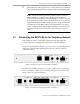
1-6 Chapter 1: Installation Table 1-1, describing the ports on the SP201-SA models, reflects the following port correspondence: • Port 1 of the two-port SP201-SA corresponds to port 1 of the four-port SP201-SA. • Port 2 of the two-port SP201-SA corresponds to port 3 of the four-port SP201-SA. Table 1-1.
Connecting the SP201-SA to the Telephony Network 1-7 Note: Regardless of port numbers or trunk numbers shown in the procedures in this document, always type the port or trunk number that corresponds to the SP201-SA port that you are configuring. Some procedures may specify separate instructions for the two-port SP201-SA and the four-port SP201-SA. However, other procedures need to show the more extensive, general case.
1-8 1.4 Chapter 1: Installation Connecting to the Power Source The SP201-SA unit has one external power supply. The external power supply receives input from a power source of 110 to 220 volts AC at 50 to 60 Hz. (The AC power supply autosenses the AC voltage.) The power supply outputs 5.5 volts DC to the SP201-SA. After completing all other connections, you can connect the SP201-SA to the power source.
Connecting to the Control Console 1-9 supplied by the customer.) Use one of the following methods to connect a control terminal to the SignalPath: • Use a direct connection described in Section 1.5.1, Connecting a Local Terminal to the SignalPath Device. • Connect over a remote modem, described in Section 1.5.2, Connecting an External Modem to the SignalPath Device.
1-10 Chapter 1: Installation Table 1-2. Communication Settings for Terminal Emulation (2 of 2) Parameter Value Data bits 8 Stop bit 1 Flow control None 3 Save and re-open the configuration. Communication between the SP201-SA and the control console is established when you open the saved configuration. 4 Next, type warmstart and press Enter. The SP201-SA will reboot. Note: If there is no readout on the control console, communication with the SP201-SA has not been established.
Connecting to the Control Console 1-11 2 On the remote side, use a serial RS232 straight-through female-DB9to-male-DB25 cable to connect an external modem to the temporary control terminal’s DB9 COM port. 3 Set the following mandatory modem setup requirements.
1-12 Chapter 1: Installation a On the SP230: Connect a serial RS232 straight-through DB25 cable to the CCI's male DB25 connector and to the external modem. (Connection to the CCI lets you communicate with the CCI’s corresponding SCM. The CCI’s serial port is physical DCE.) Note: Older versions of the CCI may have a female DB25 connector, physical DTE. In this case, one end of the cable will need a DB25 gender changer. The cable will also need a null modem adapter at the modem connector.
Connecting to the Control Console 7 1.5.2.1 1-13 At the local terminal, use the local modem to dial the remote modem’s number. When the remote modem answers, configure or manage the remote SignalPath device. Sample Settings for an External Modem This section provides settings for one type of external modem, the U.S. Robotics Sportster®. Also see Section 1.5.2.2, Sample Command Sequence for an External Modem. Table 1-3. DIP Switch Settings for U.S.
1-14 Chapter 1: Installation Table 1-5. Sample Extended Data Commands for U.S. Robotics Sportster® External Modem 1.5.2.2 Command Description &b1 serial port data rate fixed &h0 flow control disabled &k0 data compression disabled &m0 error control disabled &n6 connect speed fixed at 9600 bps Sample Command Sequence for an External Modem Table 1-6 lists a partial command sequence as an example of using the modem connection to dial into and configure a remote SignalPath.
Remote Connection to the SignalPath Device 1-15 Table 1-6. Sample Command Sequence for U.S. Robotics Sportster® External Modem (2 of 2) Command Type of Command at dt 4353 operation Local modem uses tones to dial 4353 (the remote modem’s number). +++ operation Local modem escapes to line-command mode (so that you can use the terminal to configure or monitor the remote SignalPath). operation Local modem goes on hook (that is, it hangs up on the call). Action ... ath1 1.
1-16 Chapter 1: Installation Note: The SP201-SA does not have an IP address; however, it has a direct serial connection to a local terminal. If the local terminal has an IP address and you wish to use a remote terminal to communicate with the SignalPath, you must connect the remote terminal to the SignalPath’s local terminal. 1.6.
Remote Connection to the SignalPath Device 1-17 Figure 1-4. Full Path for Remote Access to a SignalPath Device 1.6.2.1 Connection between the SignalPath and the Local Terminal The local terminal (e.g., a PC) must have a direct connection to the SignalPath device. Connect the local terminal’s COM1 port to the RJ45 Supervisory port on the front of the SP201-SA chassis. Start a terminal-emulation program (e.g., HyperTerminal).
1-18 Chapter 1: Installation The following general instructions indicate the overall process: • On the host workstation, set up an account for the client. • On the client workstation, configure the information for connection to the host. The following items are common to all connections: • Each workstation must enable a remote desktop connection. (This feature is available in Windows 2000 and above.) • Each workstation must install the software needed for the connection.
Remote Connection to the SignalPath Device 1-19 Note: Some products include a webserver so that clients can use a browser for remote management. The same process is used to establish the connection: The host must set up a client account, etc. 1.6.3 Sample Connection This guide uses the commercial product pcAnywhere to illustrate configuration of a remote connection. In pcAnywhere, the PC connected to the SignalPath device is a host. The host and the client are configured in similar ways in pcAnywhere.
1-20 Chapter 1: Installation • After the client setup has finished, right-click the icon for the client and select Properties. Then select the Advanced tab and specify the client’s privileges on the host machine. • In the host’s firewall software, indicate that the client connection may pass through the firewall. (Consult your network administrator for information on doing this.) Configure the client in the following way: • In Windows, enable remote access.