SOLO PLUS WALL MOUNTED UNITS 2001 to 2009 ISO 14001 ISO 9001
SOLO PLUS UNITS 2003 Contents Page Introduction Model Table Environmental Management Policy Disposal Requirements Wall Mounted Units Dimensions Location & Installation Wall Mount Solo Units Power Absorption Table Wall Mount Units Technical Data Access to the Unit Compartment and Evaporator Housing Controller Operation 1 1 2 2 3 3 to 4 4 5 6 6 to 7 Controller Parameters Access and Description for Models with Serial Number Ending in A, B, C, D and E Parameter List for Models with Serial Number Ending in A
For Foster spare parts information and prices go to www.fosterrefigerator.co.uk. Once you have accessed the home page select ‘Spares’ from the menu on the left hand side of the page. The screen will change to the ‘Welcome to Foster WebSpares’ page. Click on ‘Browse Product’ and from there and select the product range you require followed by the model.
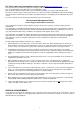
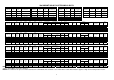
Wall Mount Units Dimensions A 735 830 830 1 2 3 1 SP101HW – 201HW – 301HW – 101LW B 790 790 982 C 264 264 364 2 SP401HW – 501HW – 201LW D 280 280 350 E 510 510 632 F 368 585 585 G 400 620 620 3 SP601HW – 301LW Location. To obtain the optimum operation of the unit the following is recommended: A) Place the unit in a room away from any heat source.
Door Opening Door Opening Door Opening Wall Mount Solo Units Power Absorption Table Compressor Model Electrical Supply Supplier Model SP 101HW SP 101HWLA SP201 HW SP201 HWLA SP301HW SP301HWLA SP301HWLARP SP401HW SP401HWLN SP401HWLA SP501HW SP501HWLA SP501HWLARL SP601HW SP601HWNG SP601HWLA SP101LW SP101LW SP101LWLA SP200LW SP201LW SP201LWLA SP201LWPS SP201LWspe SP301LW SP301LWLA SP301LWLARP SP301LWPS 230-1-50 230-1-50 230-1-50 230-1-50 230-1-50 230-1-50 230-1-50 230-1-50 230-1-50 230-1-50 400-3-50 4
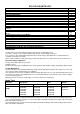
Wall MOUNT SOLO PLUS TECHNICAL DATA STORAGE TEMP +10°C Foster Model No Ref Gas Qty Grms SP 101HW R404A 0.67 SP 201HW R404A 0.67 SP 301HW R404A 0.64 SP 401HW SP 501HW SP 601HW R404A R404A R404A 1.10 0.88 1.11 STORAGE TEMP +1/4°C Capillary size No x Dia X Len Foster Model No Ref Gas Qty Grms 1 x 1.5x 2500 SP 101HW R404A 0.67 1 x 1.5 x 2500 SP 201HW R404A 0.67 1 x 1.8 x 2000 SP 301HW R404A 0.64 1 x 2.0 x 2900 2 x 1.8 x 2500 2 x 2.
ACCESS TO THE UNIT COMPARTMENT AND EVAPORATOR HOUSING Wall Model Front Panel: Condenser Fan Assembly Evaporator fan assembly Grasp each side of the front panel and “pull forward” releasing it from the spring clips located down each edge, it may be necessary to separate the front panel from the main body using a flat blade screwdriver and gently ease away. After removing the front panel “pull upwards” the condenser fan housing assembly to release it from the 4 “spring clips” located in each corner.
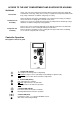
5. Display: When connected to the mains the display will read OFF indicating the condition of the unit. By pressing the ON/OFF key for 5 seconds the unit will turn ON and display the room temperature. During programming mode the various parameters will be displayed and during alarm mode an alarm code will be displayed. 6. SET/ESC key: Pressed for 3 seconds, the led is lit and setting of required room temperature is enabled. During programming it is used to pass from a sub menu to an upper one. 7.
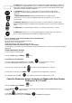
Press the UP key rE1 will be displayed. Listed are the codes and the menu they relate to in the parameter list rE1 menu = coP = Compressor rE2 menu = deF = Defrost rE3 menu = Fan = Fans rE4 menu = Luc = Light rE5 menu = ALP = Temperature Alarms rE6 menu = PP = Pressure Alarms rE7 menu = ALP = Condensing Alarm Use the up or the down key to scroll through the parameter labels. When you have made the selection press the ENTER key to access the parameters. Press the ENTER key to get to the next level.
dtY dt: dSt: Defrost type selection (timed , electric, hot gas off cycle). Range 0 to 3. 0 = Timed defrost. 1 = Electric defrost. 2 = Hot gas defrost. 3 = Off cycle. Drain down time. After the defrost has been completed the compressor and evaporator fan stay off for the duration of the fan delay period. Range 0 to 250 minutes. Defrost termination temperature. The temperature at which the defrost relay is de-energised. Range -50°C to +150°C Fans rE3 menu. FAn Fdt: FCO: dFd: Fod: Fst: Fan delay time.
Parameter List for models with serial number ending A, B, C, D and E. Label Description Display Readout °C or °F ( 0=°C. 1=°F) dro Calibration of room sensor CA1 Compressor rE1 menu. coP Differential diF Max.imum set point HSE Minimum set point LSE Time delay between 2 compressor starts dbi Timedelay between compressor OFF and next dOF start Compresor ON time if room sensor fails Ont Compressor OFF time if room sensor fails OFt Defrost rE2 menu.
Controller Alarms and Alarm Descriptions for models with Serial Number End Letter from "A" to "E" When an alarm condition occurs the unit will display an alarm code, the alarm LED will illuminate and the buzzer will sound. The alarm buzzer can be muted by pressing any of the keys but the alarm LED will continue to flash for as long as the alarm persists. Press the ENTER key for more than three seconds and FnC will be displayed.
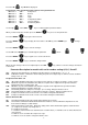
Wiring Diagram Code Identifications BA BC BS BVR BVRS E E1 M1 EP ER1 ER2 ES F13 F1 F1E F20 FL FM Room Sensor Condenser Alarm Sensor Defrost Sensor Speed Regulator Speed Regulator Sensor Defrost Heater Resistenza Carter Compressore Compressor Crankcase Heater Door Heater Circuit Control Board Heater Voltage Regulator Heater Condensate Drain Heater Voltage Regulator Fuse Compressor Fuse Electronic Control Cab Auxiliary Fuse Room Light Fuse Voltage Regulator FTE HI K1 K11 M1 MPC MVC MVE P1MX PMI PMX Q1 Q3 T
Wiring Diagrams for Models with Serial Numbers Ending in A, B or E 13
14
15
16
17
18
Parameter Modification Instruction for Models with Serial Number Ending in ‘F’, ‘G’ and ‘H’. Turn the unit ON using the ON/OFF Press and hold the ENTER key. key for five seconds.
Label CP dIF HSE LSE Ont OFt dOF dbi dEF dtY Dit dCt dEt dSt FAn FSt Fdt dt dFd FCO FOd AL AFd HAL LAL PAO dAo OAO SA3 dA3 PrE PEn PEI diS CA1 drO CnF Description Compressor Parameters Differential Maximum allowed set point Minimum allowed set point Compressor ON time if room sensor fails Compressor OFF time if room sensor fails Time between Compressor OFF and next start Time between 2 compressor starts Defrost Parameters Defrost type: 1= Hot Gas.
Wiring Diagrams for Models with Serial Numbers Ending in ‘F’, ‘G’ and ‘H’.
22
23
24
25
26
Foster European Operations France Foster Refrigerator France SA Tel: (33) 01 34 30 22 22. Fax: (33) 01 30 37 68 74. Email: commercial@fosterfrance.com Germany Foster Refrigerator Gmbh, Tel: (49) 781 990 7840. Fax (49) 781 990 7844. Email: info@foster-gmbh.de Foster Refrigerator Oldmedow Road Kings Lynn Norfolk PE30 4JU Tel: 01553 691122 Fax: 01553 691447 Website: www.fosterrefrigerator.co.uk Email: sales@foster-uk.