
User's Manual
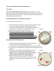
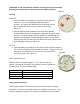


Figure 4
Figure 3
(CAUTION: make sure that the distance from the glass to be protected
and the glass break detector does not exceed fifteen (15) feet.)
Testing
Walk Test
1. Push and hold the test button for two (2) seconds and then
release it. The red LED will light while the button is
pressed. The green LED will blink once to indicate that the
unit is in auto test mode for the next 90 seconds (See
Figure 1).
2. Activate a glass break simulator in the area of the window
or windows that you are attempting to protect with the glass break
detector. The Glass Break Detector should first acknowledge the
detection of a thud sound by illuminating the green LED and then
illuminate the red LED when the unit detects the crash portion of the
glass breaking sound (See Figure 1).
RF Test
1. Push and hold the test button for five (5) seconds and then release it.
The red LED will light while the button is pressed. The green LED will
blink twice to indicate that the unit is in RF test mode for the
next 90 seconds (See Figure 1).
Glass Type/Thickness
Minimum size for all glass types is 11” x 11” (28 cm x 28 cm)
square. Glass must be framed, in a wall of the room or mounted in
a barrier of 36” (91 cm) minimum width.
Glass Type
Minimum to Maximum Thickness
Plate
1/8 in. to 1/4 in. (3.2 mm to 6.4 mm)
Tempered
1/8 in. to 1/4 in. (3.2 mm to 6.4 mm)
Sealed, Insulating
1/8 in. to 1/4 in. (3.2 mm to 6.4 mm)
Case Tamper Detection
Removing the SW-ATT-GB sensor from its base will cause the integral
transmitter to send a case tamper report to the Digital Life Controller. This
tamper condition will remain on the system until the glass break sensor is