
Installation Instructions

Introduction
Symbol Definitions
The following symbols are used throughout this manual:
Shock Hazards within the enclosure. Service should only
be performed by qualified service personnel.
Important Information intended to help the installer
avoid personal injury or property damage.
Warnings
Installation and service should be performed only by qualified
service personnel and should conform to all local codes.
To reduce the risk of electric shock or fire, do not
expose this equipment to rain or moisture.
Replace fuses only with the same type and rating as indicated
in the specifications section of this manual.
This equipment shall be installed in a manner which prevents unintentional
operation by employees, cleaning personnel, or others working in the
premises, by falling objects, customers, building vibration, or similar causes.
This equipment is not intended for use within the
patient care areas of a Health Care Facility.
To prevent impaired operation, ensure that all wiring is routed and
secured to prevent accidental open or short circuit conditions.
The system and any batteries (if used) should be tested at
least once per year to ensure proper operation.
Batteries (if used) should be maintained at an ambient
temperature of between 32 and 120 degrees Fahrenheit (0-49
Celsius) or premature loss of battery power could occur.
Test and verify output voltage before connecting the load.
General Applications
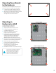
1 The power supply must be installed within the protected area.
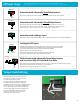
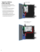
2 The LifeSafety Power Model EB-80 must be used to house the required
battery(ies) when capacities of 40 to 80 Ah are required. The EB-80 shall be
mounted within 6 ft of the power supply and the wiring enclosed in conduit.
3 Connections to the SYS FLT, AC FLT, and FAI inputs shall be completed
within the same room, not exceeding a length of 3 m.
4 Do not connect equipment to an AC power source that is controlled by a switch.
5 The power supplies shall be mounted in a UL Listed enclosure.
6 Trouble contacts shall be monitored by a listed alarm system.
The following sections cover specific
requirements based on application:
UL1076, Proprietary Burglar Alarm Applications
• The Securitron tamper switch must be
employed to monitor the power supply.
• To achieve 4 hours of standby at full load current,
80 Ah min. battery capacity is required for the
Securitron AQL102 or Securitron AQL104. To
achieve 4 hours of standby at full load current,
40Ah min. battery capacity is required for the
Securitron AQL4 and Securitron AQL6.
S319, Access Control Applications
• The Securitron tamper switch must be
employed to monitor the power supply.
For UL Compliance
• Any locking device shall be configured for fail
safe operation upon occurrence of an alarm
as shown in Activation with a Normally Closed
Relay Contact in page 3, FAI Input Usage.
FCC Information
This equipment has been tested and found to comply
with the limits for a Class A digital device, pursuant to
Part 15 of the FCC Rules and ICES-003. These limits are
designed to provide reasonable protection against
harmful interference when the equipment is operated in a
commercial environment. This equipment generates, uses,
and can radiate radio frequency energy and, if not installed
and used in accordance with the instruction manual, may
cause harmful interference to radio communications.
Operation of this equipment in a residential area is likely to
cause harmful interference in which case the user will be
required to correct the interference at his own expense.
Conventions Used
Within this Manual
Positional information (e.g. top, bottom, up, down, left,
right, etc.) is referenced with the board or enclosure in the
orientation shown in the illustrations in this manual.
2