
Owner manual


Securitron Magnalock Corp. www.securitron.com ASSA ABLOY, the global leader
Tel 800.624.5625 techsupport@securitron.com
in door opening solutions
© Copyright, 2011, all rights reserved PN# 500-10300
Page 1 Rev. D, 04/11
SECURITRON POWER SUPPLIES
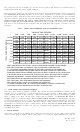
MODELS: BPS-12-3, 4.5. 6, 9 AND 15; BPS-24-2, 3, 4, 6 AND 10
OPERATION AND INSTALLATION INSTRUCTIONS
1. DESCRIPTION
These instructions cover 10 different models as shown above. The part number expresses first
the output voltage (12 or 24) and second the maximum output current capacity. For
example, a model BPS-24-6 can supply up to 6 amps at 24 volts. Securitron large power
supplies consist of a power module and CCS control board to which all installer connections are
made. The board accomplishes several functions. It provides terminals for line voltage input
and DC outputs on separate circuits, so that a number of devices can be powered. Models BPS-
12-3, BPS-12-4.5, BPS-24-2 and BPS-24-3 are furnished with the CCS-4 control board with four
separate output circuits. The other larger units in the range are furnished with the CCS-8
control board with eight separate output circuits. Each control circuit has an individual slide
switch to turn it on and off and an LED to annunciate its status. The CCS control board also
provides LED indication showing that the power supply is on, emergency release terminals, line
voltage and DC fuses and sealed lead acid - gel cell battery charging capability. All power
supplies in the BPS series are Class 2 rated when installed following these instructions.
The models which incorporate the suffix “H” in the part number have not been evaluated by UL.
These power supplies have only been evaluated by UL for use in the EXD-1 and EXD-1F FWAX
systems.
2. SAFETY
Two hazards are present in
the supply. Line voltage
input presents a high voltage
shock hazard and the
DC/battery output, represent
a high energy (current)
hazard. A shorted battery
can swiftly supply levels of
current sufficient to melt
wiring insulation and cause a
fire. To insure safety, note
first that the cover LED is on
at any time that the supply is
dangerous, which is either if
it is receiving line voltage or
if batteries are operating.
The supply enclosure must
only be opened by trained
service personnel when
the cover LED is on. Other
safety features include line voltage and DC fuses and the fact that the line voltage input
terminals are under a warning guard plate.
3. OPERATING CHARACTERISTICS
3.1 LINE VOLTAGE INPUT
110-120 VAC should be input to terminals "H", "N", "G", as shown in the drawing. This is fed to
the input of the power module through factory made connections. The line voltage current
drawn by the power supply module will be approximately half the DC output. For example, for a
4 amp power supply, the line voltage service should be able to supply at least 2 amps. Note: if
the suffix “H” appears in the part number (i.e. BPSH-24-4), the unit requires 220 VAC input.
Apart from this change, all other characteristics are the same.