
Owner manual


PN# 500-10300
Page 5 Rev. D, 04/11
the emergency release terminals are opened, battery power will, however, be blocked just as
normal power from the power supply would be.
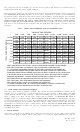
The components utilized on the CCS board for battery charging function for battery packs up to
20 amp hours in capacity whether 12 or 24 volts. Larger battery packs can be handled but
Securitron must be informed so that the board may be modified. Consult (Figure 3) to calculate
the correct battery pack based on desired backup time and the current drawn by the load. For
proper battery charging, the power supply must be set at 27 volts for a 24 volt system,
and 13.5 volts for a 12 volt system. Securitron power supplies are factory set to this level
and if it is not maintained, the batteries will not hold their full capacity, and may even be
damaged.
FIG 3: CHART TO DETERMINE SIZE OF BATTERY PACK
MIN 1 HR 2 HR
4 HR
8 HR 16 HR 24 HR 48 HR 72 HR
UL STD.
150 MA
300 MA
500 MA
1 A
2 A
3 A
4 A
5 A
7.5 A
10 A
4 AH
4 AH
4 AH
4 AH
4 AH
4 AH
4 AH
4 AH
4 AH
4 AH
4 AH
4 AH
4 AH 4 AH
4 AH
4 AH
4 AH 4 AH
4 AH
4 AH
4 AH
4 AH
4 AH
4 AH 4 AH
4 AH 4 AH
4 AH
8 AH
8 AH
8 AH
8 AH
8 AH
8 AH
12 AH
16 AH
20 AH
12 AH
12 AH
16 AH
16 AH
20 AH
16 AH
20 AH
12 AH
20 AH
12 AH
20 AH
12 AH
20 AH
8 AH 8 AH 12 AH
12 AH 16 AH
16 AH
24 AH
36 AH
24 AH
24 AH
36 AH
28 AH
28 AH
24 AH
36 AH
48 AH
36 AH
44 AH
72 AH
100AH
24 AH
32 AH
40 AH
60 AH
72 AH
52 AH
72 AH
84 AH
130AH
180AH
48 AH
72 AH
100AH
120AH
180AH
240AH
48 AH
100AH
150AH
200AH
240AH
360AH
480AH
72 AH
150AH
240AH
300AH
360AH
480AH
720AH
BACKUP TIME DESIRED
TOTAL CURRENT DRAWN
"MIN" TIME REFERS TO FACILITY USING A GENERATOR WHERE THE BATTERIES
ARE ONLY REQUIRED TO OPERATE THE SYSTEM FOR A FEW MINUTES
U.L. STANDARD REQUIRES 4 HOURS OF BATTERY OPERATION FOLLOWED BY
A 24 HOUR RECHARGE PERIOD AND THEN A SECOND 4 HOURS OF OPERATION
STANDARD SECURITRON POWER SUPPLIES CAN ONLY CHARGE UP TO A 20AH PACK.
MODIFIED EQUIPMENT. LARGER PACKS ARE SHOWN IN ITALICS IN THE CHART.
IF A LARGER PACK IS CALLED FOR, THE FACTORY MUST BE ALLERTED TO SUPPLY
BATTERIES MUST BE SEALED LEAD ACID OR GEL CELL TYPES.
DRY CELLS WILL NOT RECHARGE AND WILL BE DAMAGED.
THIS CHART IS ONLY VALID IF BATTERIES ARE OPERATED
AT ROOM TEMPERATURE. IN A COLD ENVIRONMENT, CAPACITY IS REDUCED.
BATTERIES SHOULD BE REPLACED AFTER 5 YEARS OF USE.
3.7 CODE APPROVED WIRING METHODS
Note that these units are Class 2 rated. This means that the individual DC outputs of the
supplies (on “P” terminals) are current limited and can pose neither a high voltage nor high
energy hazard outside of the enclosure. Electrical building codes in most jurisdictions permit
Class 2 wiring to be done “in the open” rather than in conduit. To maintain the Class 2
ratings on the “P” terminal outputs, never connect them together to obtain higher capacity.
If you require higher capacity use the “H” terminal but the “H” terminal is high current (not Class
2) and generally must be in conduit. The line voltage wiring coming into the unit also must
generally be in conduit as it poses a high voltage hazard. Be sure to check with your local
building department to make sure you are complying with applicable wiring codes before
installing these units.
4. SLAVE BOARD
Your power controller may include more than one CCS board. If so, the other boards will be
"slave" boards (part # CCB-8) whose only purpose is to provide eight additional "P”, and "R"