
Installation Instructions
PN# 500-19400
Page 2 Rev. E, 02/11
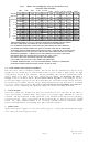
Therefore any supply which is operated at its nominal voltage (12 or 24 v) can supply about
20% more than its rated current. Despite this, we strongly recommend that supplies be
operated substantially below their maximum output capability. Operating power supplies at
their maximum greatly increases the possibility of heat induced failure. "Margin for error" is lost
and this is inappropriate for a security system. Power supplies should be run at no more
than two thirds of their maximum capacity for optimum reliability.
3.3 EMERGENCY RELEASE (FIRE ALARM) TERMINALS
If the power module is operating or if batteries are operating, the red LED will illuminate. +V
(12 or 24VDC depending on the model power supply) will then be on terminal F1. A connection
must then be made between terminals F1 and F2 (this will turn on a power relay) before +V is
routed to the "P" terminals. Terminals F1 and F2 therefore constitute an emergency
release point. If desired, for instance, NC contacts controlled by the user's fire alarm system
can be connected across terminals F1 and F2 such that the connection between these terminals
will be broken in the event of a fire. UL listed auxiliary latching normally closed contacts
(minimum switching capability of 75 mA) from the fire alarm system should be used.
"Trouble" contacts must not be used. This will automatically release all the devices being driven
by the unit. If the emergency release terminals are not to be used in this way, a jumper should
be placed between them so that the board's output terminals will function.
Terminal FA is a free parking terminal.
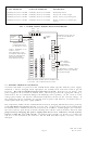
3.4 OUTPUT TERMINALS
The CCS8M board has three types of output terminals. “P” terminals are on individual circuit
breakers and carry +12 or +24 volts on them (when the emergency release terminals are
closed). The “H” terminal carries the full +V output of the supply on a single terminal (when
F1 and F2 are closed). Use the “H” terminal for applications where the device being powered
requires more than 2 Amps of current. The Polyswitch circuit breakers cannot reliably supply
more than 2 Amps of current without tripping and you should never wire multiple “P”
terminals in parallel to supply increased current. This bypasses the safety role of the
Polyswitch breakers and also does not work very well. When two “P” terminals are wired in
parallel, current carrying capacity is not doubled. The current conducted through the two
terminals will not be identical so one switch will break first and then the second will immediately
trip. When “P” terminals are correctly used as isolated outputs, each is inherently current limited
to Class 2 standards. Always use the “H” terminal for applications requiring high current.
Finally, the “R” terminals are all for 0 volt DC negative return and are in common.
3.5 SUPERVISION
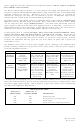
During normal operation both trouble reporting relays are energized (refer to Voltage
Supervision Diagnostic Table on page 4). To report loss of AC, connect corresponding wiring to
terminals marked AC FAIL (If AC line voltage is present, there will be continuity between the C
and NO terminals). To report low battery, connect corresponding wiring to terminals marked
LOW BATT. During battery operation and AC line voltage not present, there will be continuity
between the C and NO terminals. If during battery operation the battery voltage drops below
10.4VDC (20.8VDC for the 24V power supplies) the battery will automatically disconnect to
prevent possible damage to the battery. Once the battery has been automatically
disconnected, AC line voltage must be restored before the battery is again available
for backup. All relay contacts have transient/surge absorbers to protect the board from
external high voltage transients. The maximum voltage allowed on any pair of relay
contact terminals is 30VAC or 38VDC.
3.6 FUSING AND CIRCUIT POLYSWITCHES
An AC fuse, DC fuse and eight Polyswitches are present on the board. The AC fuse is on the
hot 120 VAC input and protects against an internal short in the power supply transformer. A
short in the DC load will not blow the AC fuse. The DC fuse protects the full DC output of the
supply prior to it being divided through the Polyswitches to the individual “P” outputs. The
Polyswitch is a special type of automatic circuit breaker. If one of the Polyswitches receives an
overload, it will rapidly cut the current down to a small leakage current (about 100 mA) which
will allow the other outputs to continue to operate
. Note that each “P” output includes a
slide switch and LED. The slide switch can cut DC power to its respective output and the LED
monitors when the output is powered. In the event of one of the Polyswitches tripping, the
associated LED will go out or dim. If all the LED’s go out, one of the fuses has tripped or the