
Spec Sheet


PN# 500-22700
Page 15 Rev. F, 03/11
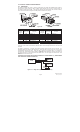
4 REASSEMBLE END MOUNT ASSEMBLY
IF
the PC board and plunger slide out of
the end mount:
1. Insert connector of power cord through
wire feed thru hole in the end mount and
assemble the end mount to the base riser
as shown.
2. Using a #1 Phillips screwdriver,
reassemble the spring plunger housing to
the base assembly as shown. Do not
overtighten screws! – they may strip
the holes in the plastic base riser.
NOTE: The PC Board is glued to the plunger
housing which is a spring loaded assembly.
If the PC board/plunger ever become
dislodged from the end mount assembly:
Reinstall spring and plunger into the housing.
Align PC board into slotted rails of end mount.
Compress spring into housing to clear the base
of the end mount while carefully sliding the PC
board back into potion.
Reinstall two (2) screws.
5 ASSEMBLE BAR TO DOOR
1. Plug the power cord connector into the
receptacle on the PC board.
2. Insert the end mount assembly with the PC
board attached back into the end of the bar.
3. Reinstall the shipping clip if necessary to
hold the bar together throughout the
remaining installation process.
4. Install the DSB to the door as prescribed in
the DSB installation and operation
instruction manual. (After the bar has been
installed, the shipping clips may be
removed).
5. Drill a 3/8” diameter hole in the door frame
adjacent to the bar end mount as shown.
6. Install door cord insert over end of power
cord and slide up and into the loose end of
the flexible door cord shield.
7. Pull power cord through frame and make
electrical connections.
8. Install the door cord cap over the power
cord and door cord shield as described in
the DSB installation and operation manual.
PC Board
Rece
p
tacle
Power Cord
Connecto
r
Door Cord Cap
Power Cord through
3/8” diameter hole
in frame
Door Cord
Insert
Door Cord
Shield
End Mount
Connecto
r
Screws
Screws
Spring
Plunger
Housing
Spring
Plunge
r