
Spec Sheet


PN# 500-22700
Page 8 Rev. F, 03/11
8. ELECTRICAL CONNECTIONS AND WIRING
8.1. DSB WIRING
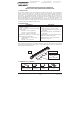
The DSB is supplied with either a 16-foot [4.88 meter] long cable with traditional wire leads or
an ElectroLynx wiring harness. Either of these wiring devices may be used to connect power to
the main PC board of the DSB. The following figures and table identify the contact numbers,
wire colors and functions assigned for DSB power and DPST relay output:
Figure 10
Traditional Wiring Connector ElectroLynx Wiring Connector
Connector
Contact
Number
Wire Color Function
Connector
Contact
Number
Wire Color
Function
1 Red Positive (+) 1 Black Common (-)
2 Black Common (-) 2 Red Positive (+)
3 Orange Normally Open #1 3 White Normally Closed #1
4 Blue Normally Open #2 4 Green Normally Closed #2
5 White Normally Closed #1 5 Orange Normally Open #1
6 Green Normally Closed #2 6 Blue Normally Open #2
7 N/A Not assigned 7 N/A Not assigned
8
N/A Not assigned 8 N/A Not assigned
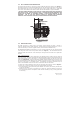
The male connector of the cable or ElectroLynx wire harness is plugged into the 8-pin female
connector on the main circuit board so that the cable routes directly back into the end mount of
the DSB.
The DSB is operated by a control relay which changes state when the bar is touched. For
additional safety the DSB is a fail safe device. When the DSB receives power, the control relay
automatically energizes the lock. When the bar is touched, it changes state. For releasing a
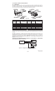
magnetic lock, the following wiring diagrams (Figures 11 and 12) show typical connections of
the dual sense bar, power supply and a fail safe lock in use on single and double door exits
without an access control unit.
THE WHITE (NC1) WIRE MUST ALWAYS CONNECT TO THE INCOMING (+) POWER WIRE
FOR THE BAR TO OPERATE CORRECTLY.
Figure 11 – Single Door (No Access Control Unit)