
Installation Instructions

Securitron Magnalock Corp. www.securitron.com ASSA ABLOY, the global leader
Tel 800.624.5625 techsupport@securitron.com
in door opening solutions
© Copyright, 2012, all rights reserved PN# 500-11800
Page 1 Rev. D, 10/12
SECURITRON PRIME TIME MODEL DT-7
INSTALLATION AND OPERATING INSTRUCTIONS
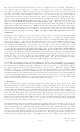
1. DESCRIPTION
Securitron's Prime Time is a daily or weekly digital timer which operates on 12 to 24 volts AC or
DC and energizes and deenergizes a 10 Amp double pole, double throw relay according to
instructions set over a week. Toggle, or 2 types of pulsed relay operation may be selected.
2. POWER UP AND TIME SETTING
Identify terminals 1 and 2 marked "12-24 AC/DC". Apply a voltage source in this range to these
2 terminals. If a substantially greater voltage is applied the unit will be damaged.
Current drawn is 160 mA when the unit's relay is energized and 10 mA when the relay is
deenergized regardless of input voltage. Note that if DC voltage is used for power, polarity is
unimportant.
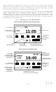
When power has been applied, the liquid crystal display on the rectangular plastic timer module
will come on showing the word "off" and "0000". The next step is to input the current time of
day into the timer module. To set the time of day, push and hold down the button farthest on
the left which shows the clock symbol. While holding this button down, set the hours by
repeatedly pushing the "H+" button. Note that if this button is held down, the hours will
automatically increment. Note also that the unit does not use AM and PM designation for the
hours, but rather employs military time based on a 24 hour system. For example, 22:00 hours
is the same as 10:00 PM.
In similar fashion, set the minutes by depressing the "M+" button while holding down the clock
symbol button. Finally, set the day of the week by pressing the day button while holding down
the clock symbol button. Once the time of day and the day of the week have been entered you
can release the clock symbol button.
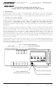
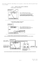
FIG. 1: PRIME TIME OVERVIEW
BATTERY CLIP (AA CELL)
BACKS UP DISPLY MODULE
OBSERVE POLARITY
J1
J2
J3
SELECT TOGGLE MODE
SELECT DOUBLE PULSE MODE
SELECT SINGLE PULSE MODE
CC
NO
NO
NC
NC
DRY, DPDT, 10 AMP RELAY CONTACTS
1
2
3
4
FIRST MAN IN TERMINALS
BOARD POWER
12-24 VOLTS AC OR DC
NOTE: IF JUMPER BLOCK IS
MISSING, UNIT WILL NOT FUNCTION
SEE PARAGRAPH 6
Timer
Day
h+ m+
Reset