EcoPower™ Power Supply Owner’s Manual 1 500-33530, Rev B
Table of Contents Warranty .................................................................................................... 2 Models ....................................................................................................... 3 Structure .................................................................................................... 3 Block Diagram ........................................................................................... 4 Specifications .................................
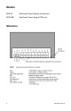
Models EPS-05 EcoPower Power Supply in Enclosure EPS-05B EcoPower Power Supply PCB only Structure 3 500-33530, Rev B
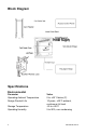
Block Diagram Specifications Environmental Parameter Operating Ambient Temperature Design Product Life Storage Temperature Operating Humidity 4 Value 0 to +49° Celsius (C) 10 years, +49°C ambient, continuous full load -25 to +85°C 5 to 90%, non-condensing 500-33530, Rev B
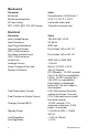
Mechanical Parameter Enclosure Enclosure dimensions AC input wiring DC1, LOCK, BAT, FAI, ACC wiring Value Polycarbonate, UL294 Level 1 4 1/8” X 4 1/8” X 3 13/16” 3-wire with strain relief 10-position terminal strip Electrical Parameter Input Voltage Range Input Frequency Input Surge Resistance Access Control Input VDC, 0.02A minimum Fire Alarm Interface Input VDC, 0.
Output Voltage Ripple and Noise Output Surge Resistance Output Over Voltage Protection Battery Type and Capacity Battery Standby Time Total Load Current 20 mA 50 mA 100 mA NOTE: < 0.14 Vpp (20 MHz bandwidth limit measurement) 2400 Vpk Under any single point condition, output voltage shall not exceed 120% of nominal voltage Sealed Lead Acid (SLA), 12V, 0.8 Ah 20.5 hours dependent on lock type (FSA or FSE) and usage.
Regulatory Compliance • EN60950-1:2006+A11:2009+A1:2010+A12:2011, "Information Technology Equipment–Safety” • FCC Part 15, Subpart B, "(unintentional radiator), Class A for industrial and commercial use" • EN55022:2010, "Class A for industrial and commercial use” • EN55024:2010 • EN61000-3-2:2006+A1:2009+A2:2009 • EN61000-3-3:2008 • CE LVD and EMC directives currently in effect • EU RoHS Directive • EU REACH Regulation UL294 Access Control Performance Levels for Model EPS-05 Power Supply N
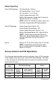
Status Signaling Green LED Signaling AC Power Mode: Solid on AC Standby Mode: 2s on / 2s off AC Lost Mode: 1s on / 2s off Output Voltage Abnormal: OFF Battery Disconnected: Rapid flash (4 times per second, then off for 1 second) NOTE: Black text indicates condition; green text indicates corresponding LED lighting pattern. Red LED Signaling Power Supply Alarm Mode: ON Power Supply Normal Mode: OFF Output Voltage Abnormal: Blink at 1 Hz Battery Discharged Below 9.6V: Blink at0.
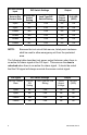
Access Control Input DIP Switch Settings Output Access Dry Contact State Access DIP Switch Setting Lock Type DIP Switch Setting LOCK Output Voltage FAI LED (RED) Open NC FSA Off Off Open NC FSE On Off Closed NO FSA Off Off Closed NO FSE On Off Closed NC FSA On Off Closed NC FSE Off Off NOTE: Because the lock circuit fails secure, listed panic hardware shall be used to allow emergency exit from the protected area.
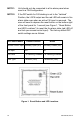
NOTE 1: Unit should only be connected to a fire alarm panel when used in a FSA configuration. NOTE 2: If the DIP switch for FAI latching is set to the “Latched” Position, the LOCK output and the red LED will remain in fire alarm state even when an active FAI input is removed. The user will need to depress the reset button on the bottom right of the front panel for 1 second (see Figure 1, “Reset Button and LED Locations”) to reset the fire alarm state (red LED off and lock per access control input).
Installing the EcoPower Power Supply NOTE 1: Installation should be performed by a qualified service person, who conforms to all local codes and complies with The National Electrical Code (or equivalent). NOTE 2: The EcoPower Power Supply can be installed in either a standard, existing 2-gang junction box (flush with the wall stud), or the included enclosure box (flush with the wall stud and drywall surface), or an enclosure surface mounted on the wall.
3. PLACE sticky shims on the side of the enclosure to be mounted to the stud. NOTE: Drilling two small pilot holes (approximately 1/16”) for the included mounting screws eases installation. 4. MOUNT enclosure to stud using the two included screws.
5. PEEL off the backing for the double-stick tape on the back of the dress ring, and PUSH the dress ring onto the enclosure.
NOTE 1: It is recommended that the conduit be installed on the top and bottom of the enclosure box for wiring and the battery be installed horizontally. NOTE 2: These products are intended to be installed with conduit fittings in the field. Connections should be used that are compatible with the Type 1 rated enclosure. 6. ENSURE wire conduit is connected to the junction box with strain relief.
11. CONFIGURE the dipswitch settings as needed for your application. 12. CONNECT AC mains power and Earth Ground, and Earth Ground connections so continuity is maintained. 13. MOUNT the cover to the enclosure using the two captive screws. Install the EcoPower Power Supply using the included enclosure box and surface mounted 1. DETERMINE location to mount the EcoPower Power Supply. 2. MARK the positioning of the 4 enclosure mounting holes on the drywall surface. 3. CUT holes for conduit, if needed.
4. ATTACH appropriate drywall anchors (one example shown). 5. MOUNT enclosure box to drywall using the screws to attach it to the drywall anchors. NOTE: It is recommended that the conduit be installed on the top and bottom of the enclosure box for wiring and the battery be installed horizontally. 6. ENSURE wire conduit is connected to the enclosure with strain relief.
10. (Optional) INSTALL power supply module back into the cover and SECURE with two installation screws. 11. CONNECT AC mains power and Earth Ground, and Earth Ground connections so continuity is maintained. 12. MOUNT the cover to the junction box using the two captive screws.
3. PEEL off the backing for the double-stick tape on the back of the dress ring, and PUSH the dress ring onto the junction box. NOTE: It is recommended that the conduit be installed on the top and bottom of the enclosure box for wiring and the battery be installed horizontally. 4. ENSURE wire conduit is connected to the junction box with strain relief.
NOTE: Wiring must be Class 1. 7. CONNECT the access control device, access control panel, fire alarm interface, battery, and lock wiring to the power supply module terminals. 8. (Optional) INSTALL the power supply module back into the cover, ensuring the LEDs are facing out at the top right, and SECURE with the two installation screws. 9. CONNECT AC mains power and Earth Ground, and Earth Ground connections so continuity is maintained 10. MOUNT the cover to the junction box using the two captive screws.
Securitron Phoenix, AZ Tel: 1.800.624.5625 Mon-Fri: 6:00am - 4:00pm PDT Fax: 1.800.232.7329 www.securitron.com techsupport@securitron.com © 2015, Hanchett Entry Systems, Inc., an ASSA ABLOY Group Company.