
Instruction Manual

PN# 500-14220
Page 4 Rev. C, 06/11
Insert and install the two (2) flush tab brackets provided using the included 6-32 x 3/8” type
“F” (self-tapping) screws.
Note: At this point, if the door was removed, it may be reinstalled.
Standard Wiring:
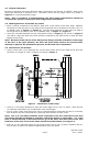
Pass the cable from the exit device being installed through the hole in the door edge.
Using a screwdriver and the four (4) 8-32 X 3/16” Phillips pan head screws and split ring lock
washers (included), assemble the flexible shield to the inside of both of the lead covers as
shown in Figure 4. Two (2) screws and washers are required at each end.
Insert the cable through the obround hole in the lead cover, feed through the flexible shield
and then out the hole of the other lead cover. Make necessary electrical connections at the
appropriate door or frame location.
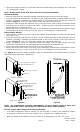
Mount each of the lead covers into place at the previously installed flush tab brackets using a
screwdriver and two (2) of the 6-32 X 3/8” type “F” (self-tapping) screws provided.
ElectroLynx® Wiring:
Insert the EL connectors at each end of the flexible shield through the obround holes inside
each lead cover.
Using a screwdriver and the four (4) 8-32 X 3/16” Phillips pan head screws and split ring lock
washers (included), assemble the flexible shield to the inside of both of the lead covers as
shown in Figure 4. Two (2) screws and washers are required at each end.
Attach the supply wiring EL connectors (from the frame) and the door device wiring EL
connectors (from the door) to the appropriate EL connectors of the EL-EPT-SC.
Insert wiring and connectors back into holes in door and frame.
Mount each of the lead covers into place at the previously installed flush tab brackets using a
screwdriver and two (2) of the 6-32 X 3/8” type “F” (self-tapping) screws provided.
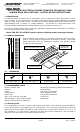
The Figure 3 illustration shows exploded views of configurations for both the solid core wood
door and hollow metal door installations.
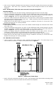
#6 X 5/8" Type "A" Screw
Lead Cover
Wood Door Installation
R 1/2" [12,7] X .075" [1,9] Deep
Lead Cover Flange Recess
6-32 X 3/8" Type "F"
Self-Tapping Screw
Lead Cover
Square or Radial Corners Okay
Countersink for #6
Flat Head Screw
Flush Tab Bracket
6-32 X 3/8" Type "F"
Self-Tapping Screw
Metal Door Installation
6-32 X 3/8" Type "F"
Self-Tapping Screw
Figure 3 Figure 4
Note: For applications involving combinations of doors/frames made of wood and
metal, follow the proper procedures as related to the door/frame material.
EPT-SC and EL-EPT-SC Special UL/Electrical Notes:
To maintain compliance with UL listings (UL 10C and UBC 7-2-1997), the maximum number
of electrical conductors to be used is twelve (12) - using No. 20-22 AWG size wire.
Electrical rating for the EPT-SC and the EL-EPT-SC is 1Amp @ 12V or 24V – AC or DC.