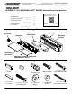
Securitron Magnalock Corp. www.securitron.com Tel 800.624.5625 techsupport@securitron.com M380BD/C/C2/X MAGNALOCK ® SERIES Installation Instructions Table of Contents Specifications 2 Configuring Options 3 Installation Guide 9 Wiring Diagram 17 Error Codes 20 Scan this QR Code for a guided installation video. Alternatively Quick Clips are available in each section.
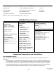
Recommended Tools Masking Tape #1 and #2 Phillips Screwdrivers Hammer Measuring Device 1/2” Open End or Crescent Wrench Pencil/Pen Center Punch Wire Strippers/Cutter Multimeter Fish Tape or Lead Wire 3/16” Hex (Allen) Wrench Drill bits: 3/16”, 7/32” (wood frames only), 3/8”, 1/2” M380BDCX Specifications Mechanical Electrical Physical Size: Height: 2.20” [56mm] Depth: 2.45” [62mm] Length: 10.00” [254mm] Shipped Weight: Weight: 6.5 lbs Holding Force (Maximum) 600 Lbs.
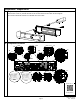
Magnalock Orientation The physical position of the camera or motion sensor (PIR) module may be reconfigured for either end of the Magnalock as desired. Or, if the unit is equipped with both camera and PIR, they may be reversed from the factory default positions. Changing the Camera and PIR Module Locations Page 3 PN# 500-23310 Rev.
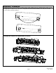
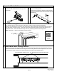
To remove or install a module, compress the legs of the support bracket and slide the bracket in or out of the retaining rails. Use a #1 Phillips screwdriver to remove, reposition, and reinstall the inserts in the cover as necessary. Page 4 PN# 500-23310 Rev.
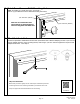
Magnalock Preparation 1. Using a Phillips screwdriver, remove the two (2) screws securing the cover as shown. Remove the cover to provide access to the circuit board on the back of the magnet. The screws should be saved to re-attach the cover later. 2. Component Locations JP4 J8 J9 J7 J2 JP1 JP3 J3 SW3 SW1 J6 J12 Quick Clip 1: BDCX Configuration Page 5 PN# 500-23310 Rev.
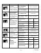
Component Label SW3 Component Name DIP Switch SW3.1: LED Enable Position 1 setting of the DIP switch enables or disables the display of the LED for lock status. SW3 SW3 Position 1 ON (default) LED Color Select ON = SECURE = RED Position 2 ON Position 2 setting of the DIP switch controls the color of the LED output. Output options are red or green. OFF = SECURE = GREEN DIP Switch SW3.2: DIP Switch SW3.3, SW3.4: DIP Switch SW3.5: PIR Model Position 5 is set by the factory.
SW1 DIP Switch SW1.4: PIR Ambient Light Compensation Can be enabled with SW1.4 SW1 DIP Switch SW1.5: External PIR Input External input at J6 can be enabled at SW1.5 JP1 Jumper 1: Alternate (REX) Output A 3-pin jumper that controls the output setting for Alternate (REX) Output at Terminal Block J7.
J8 Terminal Block 8 BondSTAT A 2-wire terminal block providing a contact in which (NO/NC) state change is determined by Jumper 3 when the BondSTAT (magnetic bond) is interrupted. Terminal Block 12 Door Position Switch A 2-wire terminal block providing a contact in which (NO/NC) state change is determined by Jumper 4 based on the magnet’s contact with the strike plate. J6 Terminal Block 6 Alternate Input A 2-wire terminal block providing a dry contact connection for external control input.
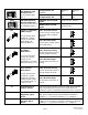
Magnalock Installation 1. CRemove two (2) screws securing lock to mounting Hbracket and slide the bracket from the top of the 1lock chassis. 2. Pinch and insert spacers flush into the dovetail slots of the lock-mounting bracket. (These spacers maintain a distance of approximately 2-3/16” from the face of the door to the back edge of the bracket). 3. Mark Mounting Holes: Use masking tape to protect the door and frame surfaces during marking and drilling.
5. Metal Door Frame - Drill Mounting Holes: Note: If installing on a wood door frame, go to Step 7. Drill two (2) 3/8” diameter holes at bracket-mounting hole marks. 3/8” diameter (METAL) Note: Do not oversize the hole. Use a step bit or pilot hole first to ensure a snug fit for the blind nuts. 3/8” diameter (METAL) 6. Blind Nut Installation: Use the tool provided to install blind nuts into each 3/8” diameter hole. Hold the collapsing nut with a 1/2” box end wrench.
7. Wood Door Frame – Drill Mounting Holes: Drill two (2) 3/16” diameter holes at bracket-mounting hole marks. Drill 1-1/4” deep. 3/16” diameter (WOOD) 3/16” diameter (WOOD) 8. Drill Wire Access Holes Drill wire access holes as needed on one (1) or both sides of the bracket location. 1/2” diameter is recommended for wire access. 9. Install Bracket: Use a Phillips screwdriver to temporarily install the bracket with spacers against the closed door.
Strike Installation 1. Close the door and place the template between the bracket spacers. Quick Clip 4: Mark the strike plate hole locations. Bracket spacers can now be removed from the bracket. Strike Installation Bracket Spacers 2. From INSIDE the door: Drill one (1) 3/8” diameter hole for the sex bolt through the door at the strike mounting center mark. Quick Clip 5: Drill two (2) 3/8” diameter x 1” deep holes at each side mark for the strike alignment roll pins. Do not drill through the door.
4. Install Roll Pins into Strike Plate: Remove the two (2) roll pins from the hardware packet. Insert a roll pin into each of the holes in back of strike. Use a hammer to gently tap into place. 5. Secure Strike Plate to the Door Apply the included thread lock compound to the 5/16-18 X 1-3/4” flat head socket screw. Pass the 5/16-18 X 1-3/4” flat head socket screw through the strike bushing, strike plate, two (2) neoprene washers, door and into the sex bolt as illustrated.
Adjustments: 1. Assemble Lock to the Bracket and Adjust: Loosen the two screws securing the mounting bracket to the door frame so that the bracket can move. Slide the lock onto the mounting bracket and test fit against the strike plate with the door closed. Slide the lock so that the entire face makes contact with the strike plate. Mark back edge of mounting bracket at each end and remove the lock from the bracket. Quick Clip 7: Adjustment 2.
3. Drill Frame for Anchor Screws: Using the mounting bracket as a template, drill the four remaining holes in the frame for the anchor screws. Metal Frames: Drill 3/16” diameter holes. Wood Frames: Drill 7/32” diameter holes. 4. Install Anchor Screws: Using a Phillips screwdriver, install the four (4) anchor screws. Metal Frames: Use #12 X 1-1/2” Type A, Phillips Pan Head Screws. Wood Frames: Use #14 X 3” Type A, Pan Head Screws. Page 15 PN# 500-23310 Rev.
Final Installation: Insert the top of the Magnalock chassis at the end of the mounting bracket. 1. Slide the lock chassis to the center of the bracket. The edge of the lock chassis must be flush with the end of the mounting bracket when centered (see inset). Quick Clip 8: Final Installation Using a Phillips screwdriver, install the two (2) 6-32 X 5/8” Phillips pan head screws to secure the lock chassis to 2. the mounting bracket. Page 16 PN# 500-23310 Rev.
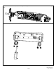
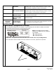
Final Wiring 1. Pull wires/cables through the wire feed-through hole(s) that are drilled in the frame. All connections to the terminal blocks may be made by pressing the locking mechanism, inserting the stripped wire into the terminal recess and releasing to lock the wire in place. The end user and installer are liable for Fire and Building code compliance. 2. The following diagram shows a basic wiring configuration for the Magnalock.
3. Motion Detector Models: Models equipped with a motion detector have control features accessed by the DIP Switches SW3 and SW1 settings (see pages 6 and 7). The relock delay timer is set with SW3.3 and 4. SW3 Sensitivity and zone width are set with SW3 Position 1,2 and 3. SW1 The PIR ambient light compensation feature is enabled/disabled using SW3 Position 4. Right Note: For increased range the motion detector sensor PC board may be repositioned in the modular bracket. Left Narrow 4.
5. After installation and wiring have been completed, re-install the lock cover through the lock chassis using the two (2) Phillips screws removed in the first step. MAGNALOCK MAINTENANCE Visual Inspection Check the rubber washers for elasticity and proper pivoting. Tighten as required. Check for build-up of debris on the Magnalock and strike armature. Check for rust on the Magnalock and strike plate armature. Clean as required.
Troubleshooting Guide: POSSIBLE ISSUES TROUBLESHOOTING TIPS No power or low power Confirm voltage and current at Magnalock to spec (see page 2) Check that the DC Power Source is Full Wave Rectified (Half wave Rectified or AC power is unacceptable) Check strike plate position and orientation Reduced Holding Force Clean surfaces and check for obstructions LED Error Codes: Note: The position 1 switch of DIP switch SW3 must be set to the ON position (LED ENABLED) for error codes to be visible.