
Installation guide

22 LCD Keypad Installation Guide
LCD Keypad Installation Guide 23
Wiring Specications
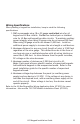
When planning a keypad bus installation, keep in mind the following
specications:
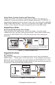
1. DMP recommends using 18 or 22-gauge unshielded wire for all
keypad and LX-Bus circuits. Do Not use twisted pair or shielded
wire for LX-Bus and keypad bus data circuits. To maintain auxiliary
power integrity when using 22-gauge wire do not exceed 500 feet.
When using 18-gauge wire do not exceed 1,000 feet. Install an
additional power supply to increase the wire length or add devices.
2. Maximum distance for any one circuit (length of wire) is 2,500 feet
regardless of the wire gauge. This distance can be in the form of
one long wire run or multiple branches with all wiring totaling no
more than 2,500 feet. As wire distance from the panel increases,
DC voltage on the wire decreases.
3. Maximum number of devices per 2,500 feet circuit is 40.
Note: Each panel allows a specic number of supervised keypads.
Add additional keypads in the unsupervised mode. Refer to the
panel installation guide for the specic number of supervised
keypads allowed.
4. Maximum voltage drop between the panel (or auxiliary power
supply) and any device is 2.0 VDC. If the voltage at any device is
less than the required level, add an auxiliary power supply at the
end of the circuit. When voltage is too low, the devices cannot
operate properly.
Refer to the LX-Bus/Keypad Bus Wiring Application Note (LT-2031) for more
information. Also see the 710/710F Module Installation Sheet (LT-0310).