
Installation guide


4 LCD Keypad Installation Guide
LCD Keypad Installation Guide 5
1K EOL
1K EOL
1K EOL
1K EOL
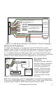
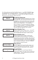
Green/White – Connect Reader Data 0
White – Connect Reader Data 1
Orange – Door Strike Normally Ope
n
Gray
– Door Strike Common
Violet
– Door Strike Normally Closed
Yellow/White
White/Yello
w
Orange White
White/Orange
Red/White
White/Re
d
Brown/White
White/Brow
n
Black – Ground
Green
– Receive Data
Yellow – Send Data
Red – Keypad Power
– Zone 4
– Zone 3
Request to Exit (option)
– Zone 2 Door Contact
(option)
– Zone 1 7/0 Panic (option)
To Keypad Bus
External Card
Reader
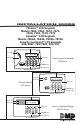
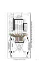
Figure 2: 12 VDC Reader Wiring for 7073/7073A/7173 and 793 Keypads
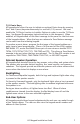
Wiring the 333 Suppressor
One Model 333 Suppressor is included with the 7073/7073A/7173 and 793
keypads. Refer to Figure 3 and install the suppressor across the 5-wire output/
reader harness Common (C) and Normally Open (N/O) or Normally Closed (N/
C). If the device being controlled by the relay is connected to the N/O and C
wires, install the suppressor on the N/O and C wires. If the device is connected
to the N/C and C wires, install the 333 Suppressor on N/C and C wires.
Door Strike Relay
Operation
As soon as the user code sent
from the reader is veried by
the panel, the keypad door
strike relay activates for 5
seconds. During this time,
the access door connected
to Zone 2 must be opened
to start the programmed
entry/exit timer and zone
Soft-Shunt.
Note: The 5-second door strike is programmable in the panel when the keypad
is used on an XR100/XR500 Series, or XR2500F panel. Refer to the XR100 Series
Program Guide (LT-0896) or XR500 Series Program Guide (LT-0679).
Figure 3: 5-wire Harness/Suppressor Installation